
Car & Motorcycle Battery Tester

The described circuit serves as a voltage monitoring system for lead-acid batteries, specifically designed for portable applications such as holiday trips or vehicle excursions. The use of the LM3914 integrated circuit enables a straightforward visual representation of battery voltage levels through a series of LED indicators.
The circuit operates by connecting the battery under test to the appropriate input terminals, which are determined by the position of switch S1. This switch allows the user to toggle between the 12 V and 6 V settings, accommodating different battery types commonly found in vehicles. When the circuit is powered, the LM3914 reads the input voltage and activates the corresponding number of LEDs based on the voltage level detected. The top LED indicates a fully charged battery, while the bottom LED signals that the battery is critically low and needs charging.
Incorporating diode D1 into the design is crucial for protecting the LM3914 from potential damage due to reverse polarity connections, which can occur if the battery is connected incorrectly. This safeguard ensures the longevity and reliability of the circuit.
For enhanced functionality, the circuit could be modified to incorporate a color-coded LED array, where each LED represents a specific voltage range. This would provide users with a more intuitive understanding of the battery's status at a glance, rather than relying solely on the position of the lit LED in a bargraph format.
Overall, this battery status monitoring circuit is a practical solution for anyone relying on lead-acid batteries during travel, ensuring that users can easily ascertain the battery's condition and take necessary actions to maintain their power supply.Most of the time a charged lead-acid battery and a power inverter would be used to ensure a smoothly organised holiday where ideally the missus and the children cheerfully use their electric and electronic gear! With rechargeable lead-acid batteries it`s invariably useful if not essential to determine whether the power source you`re hauling along on your travels is losing capacity and needs to be topped up.
The same circuit would also come in handy when going on a car or motorbike trip as it can check the status of a 12 V (car) or a 6 V (motorcycle) battery. Although the circuit draws so little power that it will not notice-ably load the battery under test, it should not be left connected permanently.
The circuit employs the familiar LM3914 (IC1) to display the voltage level. The LED readout creates a battery status readout: when the top LED lights, the battery is fully charged. When the bottom LED lights, the battery needs imminent charging! Switch S1 selects between 12 V and 6 V operation. A series diode, D1, protects the bargraph driver from reverse supply volt-age. A colour coded display with individual LEDs could be used instead of the common anode bargraph display for better indication of the state of the battery.
🔗 External reference
Related Circuits
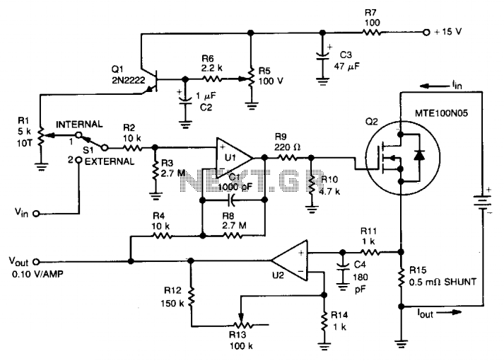
This circuit was designed for testing fuel cells, but it could also be used for testing batteries under a constant current load. It provides a dynamic, constant current load, eliminating the need to manually adjust the load to maintain...

The circuit presented is a 555 timer-based alarm system for vehicles, which primarily consists of a 555 timer and a quad 2-input NAND gate configuration. It is designed to produce a long beep sound when oil pressure is low...

The simple transistor tester in Figure 1 allows for the identification of the type of transistor and aids in detecting the emitter, collector, and base of the transistor. The simple transistor tester circuit is designed to facilitate the identification of...
When the weather is hot and the sun is shining, the car fails to start, and the radio, keyless entry, power windows, power locks, and power seats do not function. However, after sunset, everything operates normally. It is important...
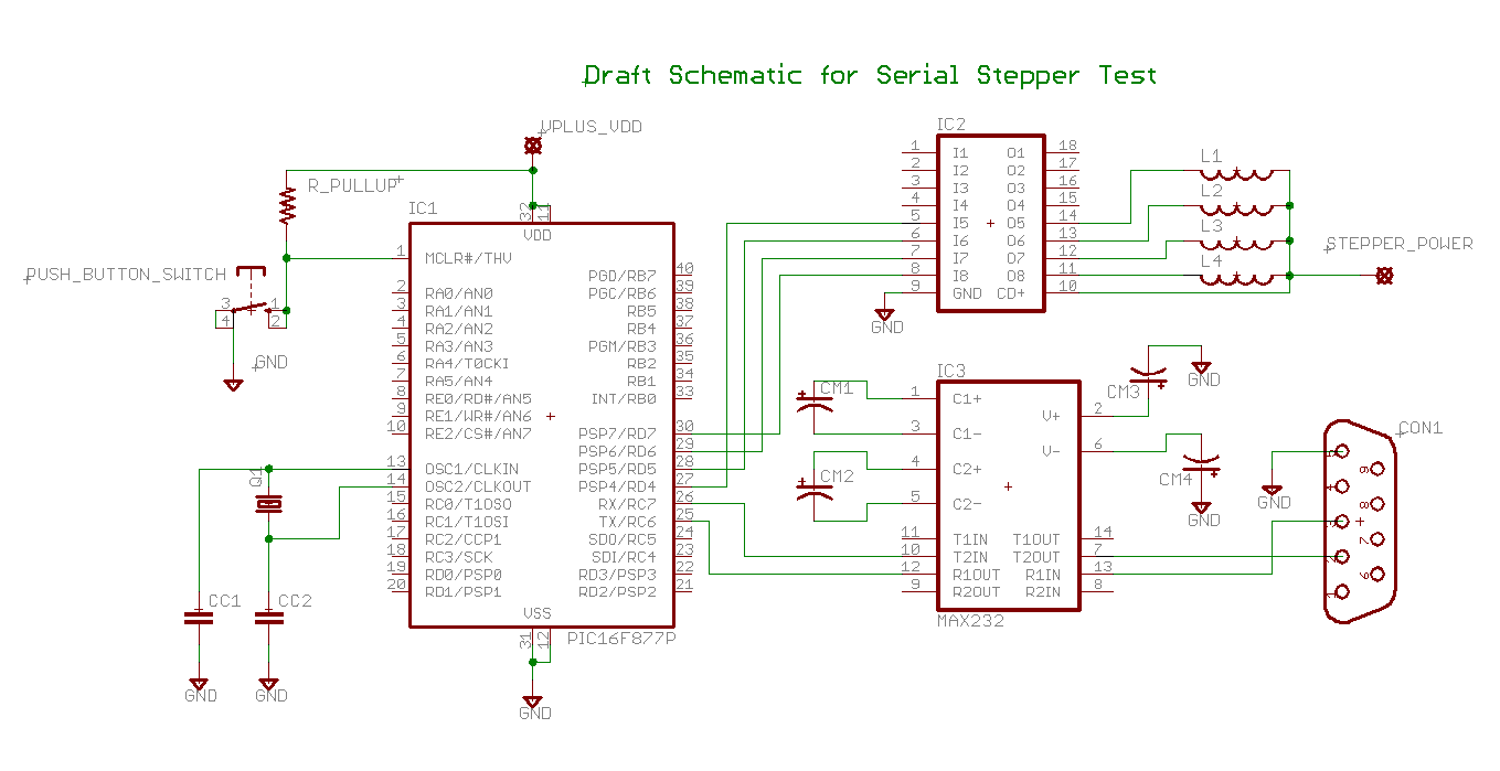
Determining the identification of drive wires on a unipolar stepper motor, which is commonly found in surplus or salvaged equipment. The platform utilized is a PIC16F877A microcontroller programmed with BoostC, interfaced via RS232 to a PC running a terminal...
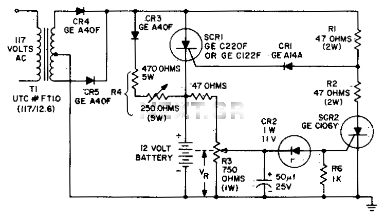
The circuit is designed to charge a 12-volt component selection at a maximum current of six amperes. Once the battery voltage reaches its fully charged level, the SCR shuts off, and a trickle charge, determined by the resistance value...