
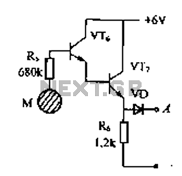
Burglar alarm bell
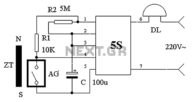
The described circuit utilizes a shaped permanent magnet (ZT) and a normally closed reed switch (AG) to create a security system that activates an alarm (DL) when unauthorized access is detected. The permanent magnet is strategically placed on the door, while the reed switch is fixed to the door frame, allowing for a reliable detection mechanism that is triggered by the movement of the door.
In the default state, the proximity of the magnet to the reed switch keeps the switch contacts open, which results in a high voltage signal on pin 5S. This high signal ensures that the internal circuitry of the alarm module remains inactive, thereby preventing any false alarms during normal use. The system is designed to operate in a low-power state, conserving energy when not in use.
Upon the intrusion, as the door opens and the magnet moves away from the reed switch, the contacts of AG close, causing the voltage at pin 5S to drop to a low state. This transition activates the internal circuitry of the module, which in turn powers the alarm (DL). The alarm emits a loud sound to alert the owner of the breach, effectively deterring potential intruders.
The delay feature incorporated into the circuit is vital for preventing nuisance alarms. The combination of resistor R2 and capacitor C creates a time delay that allows the system to remain in an active state for a brief period, even after the door is closed. This ensures that if the door is closed quickly after an intrusion, the alarm will still sound for a specified duration before the system resets itself.
Overall, the design of this circuit is both practical and efficient, utilizing simple components to create an effective security solution. The integration of the permanent magnet and reed switch allows for a reliable operation, while the delay mechanism enhances the user experience by minimizing false alarms. Circuit operation principle of the device shown in Fig. Shaped permanent magnet mounted on the door ZT activity, normally closed reed AG mounted on the door frame. Usually ZT c lose to AG, so that the two contact pieces open within AG, at this time of 5S foot was high, the modules internal circuitry is turned off, bells DL does not work. Sleep night after the owner, if a person comes into the room, and will inevitably lead to ZT AG away, within two contacts reset AG collapsed, so 5S module pin goes low, the internal circuit opened, DL power of work, issued a loud alarm sound.
Not the door is closed again, the alarm will not stop immediately, since delay action R2, C, the circuit will still work for some time stops automatically.
Related Circuits
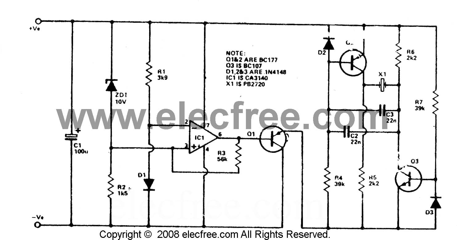
To check the battery in a car, an easy circuit utilizing the IC CA3140 and a transistor is employed. The voltage level of an automobile battery is influenced by many factors, and if it is high... The circuit for checking...
This simple alarm timer circuit is constructed using a 4060 integrated circuit, which features a stable oscillator with a relatively wide frequency range. The alarm timer circuit utilizes the CD4060 IC, which combines a low-frequency oscillator and a binary counter....
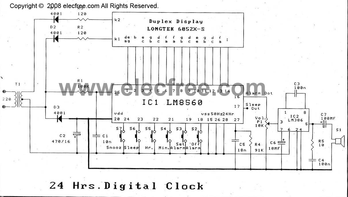
The digital time clock circuit is of great interest to electronic amateurs. The most popular clock ICs include the LM8361 and MM5387. Unfortunately, these ICs... The digital time clock circuit serves as an essential component for various electronic applications, providing...
Delay electronic doorbell circuit - touch doorbell amplifier circuit The delay electronic doorbell circuit is designed to provide a user-friendly interface for doorbell activation, utilizing a touch-sensitive amplifier circuit. This circuit typically incorporates a touch sensor that detects user interaction,...
The 555 timer IC can be of various types, all of which are pin-compatible. However, some CMOS variants may lack sufficient power to drive a transistor, in which case a standard 555 timer should be used. If a 12V...
One day, an individual contemplates the necessity of purchasing an alarm installation system when it is possible to create one independently. The common rationale against this is a lack of skills or time. However, in this case, the preference...