
Timer with Alarm Circuit

The alarm timer circuit utilizes the CD4060 IC, which combines a low-frequency oscillator and a binary counter. The oscillator generates a clock signal that drives the counter, enabling the timing function of the circuit. The frequency of the oscillator can be adjusted by varying the resistor and capacitor values connected to the timing pins of the 4060. This flexibility allows for a wide range of timing intervals, suitable for various applications.
The output of the counter can be configured to trigger an alarm or indicator once a predetermined time has elapsed. This is accomplished by connecting the appropriate output pin of the CD4060 to an alerting device, such as a buzzer or LED. The design can be further enhanced by incorporating additional components, such as a transistor, to drive higher power devices or to create a more complex alarm system.
Powering the circuit typically requires a DC voltage source compatible with the 4060, usually ranging from 3 to 15 volts. Proper bypass capacitors should be included near the power supply pins to ensure stable operation and reduce noise. The entire circuit can be compactly laid out on a PCB, facilitating easy integration into various electronic projects or systems.
Overall, this simple alarm timer circuit demonstrates the versatility of the CD4060 IC in timing applications, providing a reliable and adjustable solution for generating alarms or notifications based on time intervals.This simple alarm timer circuit is made with 4060 which has an integrated oscillator with a good stability with a relatively wide frequency range. In the c.. 🔗 External reference
Related Circuits
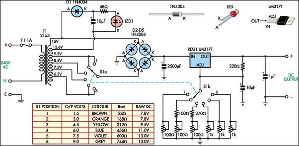
The following circuit illustrates a Battery Replacement Power Supply Circuit Diagram. This circuit is based on the LM317 integrated circuit. Features include the ability to replace... The Battery Replacement Power Supply Circuit utilizes the LM317 voltage regulator to provide a...
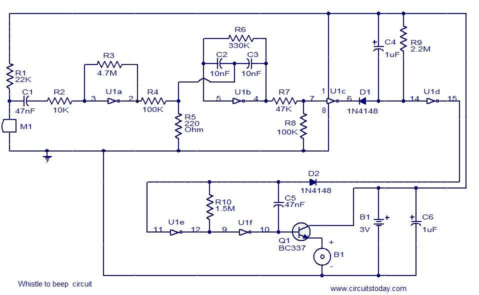
This simple circuit produces a beeping sound that lasts for approximately 3 seconds whenever a whistle is made. The CMOS Hex inverter CD4049 serves as the core component of this circuit. Among the six inverters in the CD4049, U1a...

This design outlines a phone bug circuit. The wireless telephone line spy circuit is capable of transmitting phone conversations to a nearby FM radio. The circuit must be connected to a standard phone line. In the circuit, the first...
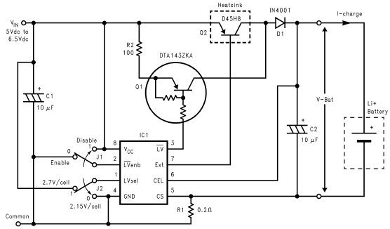
Lithium-ion charger circuit design electronic project using LM3632 controller. The lithium-ion charger circuit utilizing the LM3632 controller is designed to efficiently charge lithium-ion batteries while ensuring safety and longevity. The LM3632 is a highly integrated, step-down linear charger specifically tailored...
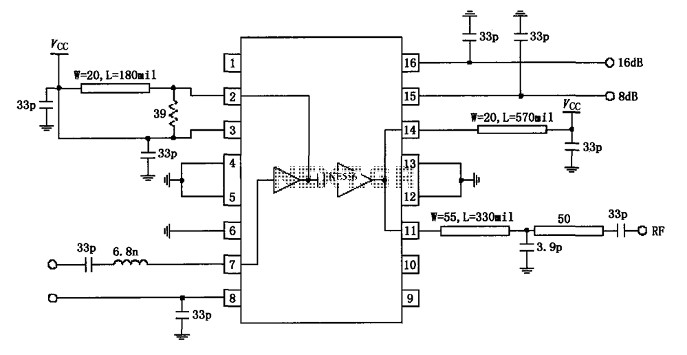
The circuit diagram illustrates the application of a 915MHz RF2155 power amplifier. The radio frequency (RF) signal enters through pin 7, where it is processed by a preamplifier. The output from the preamplifier is further amplified by the power...
The circuit of the unit is relatively straightforward; however, setting it up can be somewhat challenging. The difficulty arises from the need for matched FETs, which are not easily obtainable. Therefore, it was essential to ensure that the circuit...