
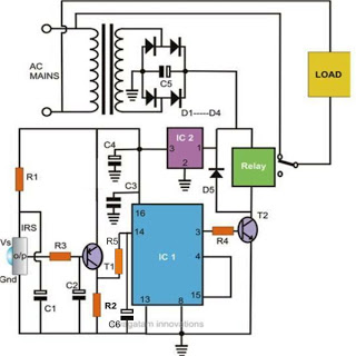
Delay electronic doorbell circuit - touch doorbell amplifier circuit
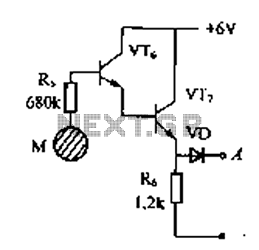
The delay electronic doorbell circuit is designed to provide a user-friendly interface for doorbell activation, utilizing a touch-sensitive amplifier circuit. This circuit typically incorporates a touch sensor that detects user interaction, triggering the doorbell chime after a predetermined delay. The delay feature allows the user to ensure that the circuit does not activate immediately upon touch, providing a buffer period that can help prevent accidental triggering.
The circuit generally consists of several key components: a touch sensor, a microcontroller or timer IC to manage the delay, a power supply, and an output driver connected to the doorbell chime. The touch sensor can be a capacitive or resistive type, which detects changes in capacitance or resistance when a user touches the designated area. The microcontroller or timer IC is programmed to initiate a delay sequence upon receiving a signal from the touch sensor.
Upon activation, the microcontroller starts a timer that counts down the specified delay time. Once the delay period elapses, the microcontroller sends a signal to the output driver, which energizes the doorbell chime. The output driver may consist of a relay or a transistor, depending on the power requirements of the chime. The power supply must provide adequate voltage and current for all components, ensuring reliable operation.
In summary, the delay electronic doorbell circuit with a touch doorbell amplifier enhances user experience by integrating touch sensitivity and delay functionality, making it a practical solution for modern doorbell applications.Delay electronic doorbell circuit - touch doorbell amplifier circuit
Related Circuits
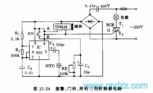
The controller circuit illustrated in Figure 15-24 consists of a switch-type Hall integrated circuit DN838 and an astable multivibrator, which is based on the 555 timer IC. This circuit is suitable for various applications, including automatic door opening, delay...
%2BCircuit%2Bdiagram%2Busing%2BCD4047%2Band%2BIRFZ44%2Bpower%2BMOSFET.png)
This simple low-power DC to AC inverter circuit converts 12V DC to either 230V or 110V AC. By making simple modifications, it is also possible to convert 6V DC to 230V AC or 110V AC. This inverter can be...
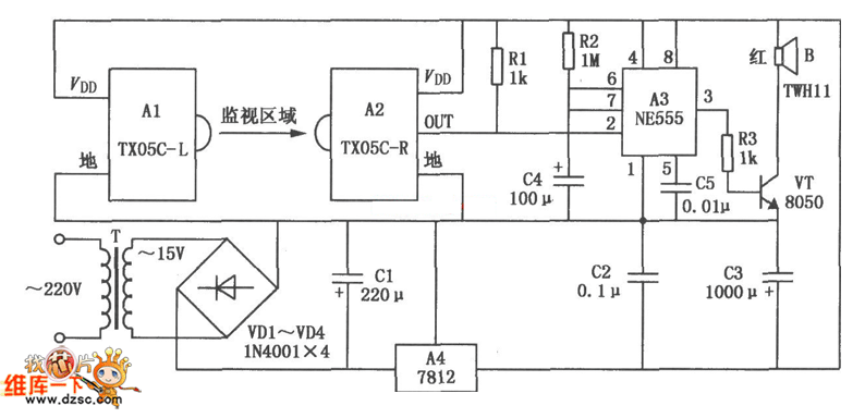
The TX05C-R infrared surveillance alarm circuit is designed for monitoring walls, windows, doors, and various restricted areas. When an intrusion occurs, the alarm activates to enhance security. The circuit comprises a transmitter module, a receiver module, a time-base circuit,...
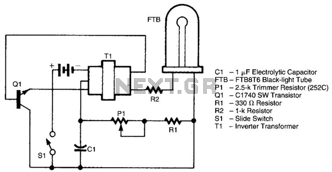
The battery-operated black light utilizes a U-shaped, unfiltered black-light tube, which requires approximately 250 Vac for operation. To generate the 250 Vac from a 6-V battery, the circuit employs a one-transistor blocking oscillator that drives a ferrite inverter transformer....
Controlling household electrical gadgets or any electrical equipment remotely can be enjoyable. While using a remote to control devices like a TV or DVD player is a common experience, managing other domestic appliances such as water pumps and lights...
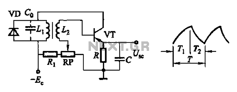
Common non-sinusoidal oscillator circuit, waveform and frequency formula - pulse wave oscillator - single-junction transistor blocking oscillator. The common non-sinusoidal oscillator circuit described is a pulse wave oscillator that utilizes a single-junction transistor in a blocking configuration. This type of...
Warning: include(partials/cookie-banner.php): Failed to open stream: Permission denied in /var/www/html/nextgr/view-circuit.php on line 713
Warning: include(): Failed opening 'partials/cookie-banner.php' for inclusion (include_path='.:/usr/share/php') in /var/www/html/nextgr/view-circuit.php on line 713