
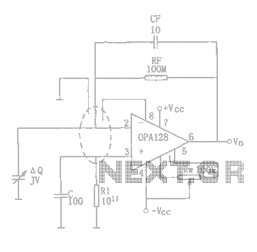
Charge amplifier circuit diagram OPA128
A charge amplifier serves a critical role in signal processing, particularly when dealing with piezoelectric sensors that generate minimal charge output. The fundamental operation of a charge amplifier relies on its ability to convert the charge signal into a voltage signal while maintaining high fidelity. The high input impedance of the charge amplifier ensures that the sensor's output is not loaded, preserving the integrity of the signal.
The OPA128 operational amplifier is specifically chosen for its characteristics that align well with the requirements of charge amplification. With a low input bias current and high input resistance, the OPA128 minimizes any additional noise or distortion that could arise from the amplifier itself. This is crucial in applications where the signal levels are very low, as even minor perturbations can lead to significant inaccuracies in the output.
In the schematic, the charge amplifier configuration typically includes the OPA128 connected in a feedback loop that allows for the transformation of the input charge signal into a proportional output voltage. The feedback capacitor is a key component, as it determines the gain of the amplifier based on the charge it receives. The design must ensure that the selected feedback components are optimized to match the characteristics of the piezoelectric sensor being used.
Overall, the design of a charge amplifier circuit utilizing the OPA128 is essential for applications requiring precise measurement and amplification of low-level signals from piezoelectric devices. This configuration provides a reliable solution for accurately capturing and processing these signals in various electronic systems.The so-called charge amplifier means for amplifying the signal charge from the piezoelectric device amplifying circuit . Such high internal impedance of the amplifier signal source, while its charge very weak signal, the current source is formed only pA level, which requires a charge amplifier with a high input resistance and low bias current, otherwise when the amplifier bias current and signal current is similar to the bias current signal may be overwhelmed, and can not achieve normal zoom. Further, high-impedance (1012 ) in the usual sense amplifier circuit can not be used. Often used for this type of electrostatic integrated operational amplifier OPA128 amplifier circuit composed.
As shown for the charge amplifier OPA128 constituted.
Related Circuits
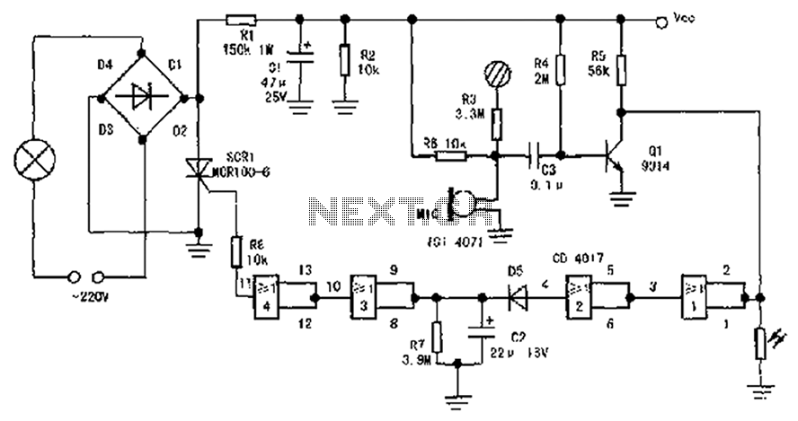
The circuit diagram illustrates a sound, light, and touch-controlled delay self-extinguishing switch. It comprises three main sections: the power circuit, the signal conversion detecting circuit, a delay circuit, and a control circuit. 1. Power Circuit: This section consists of...
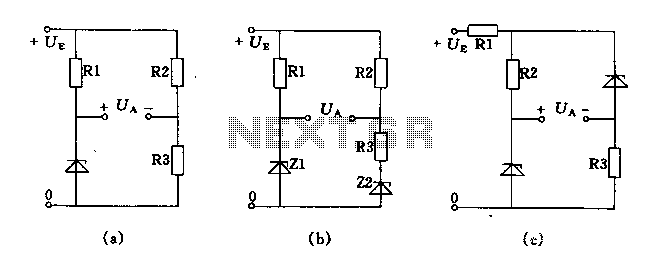
The circuit depicted in Figures A, B, and C demonstrates a high voltage coefficient. When the regulator resistance \( r_z \) is held constant, the bridge configuration achieves an infinite voltage coefficient. In Figure A, the load circuit is...
The ping of the cymbals, crack of the snare drum, thonk of the bass - none of these comes through on my low-budget speakers. Sometimes they sound so fuzzy I want to hide behind the couch until it’s over....
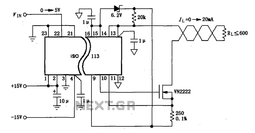
The circuit depicted in the figure consists of an ISO113 current loop isolation drive circuit that operates with an input signal (VIN) to provide an isolated amplified output of 0 to 20 mA. This current is transmitted to the...
A modulated current is supplied by the integrated rotational speed sensor KMI 15/x. This current signal needs to be converted into a ground-referenced voltage signal. The KMI 15/x sensor operates by generating a modulated current proportional to the rotational speed of...
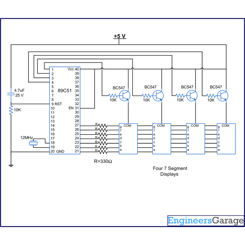
A digital clock displays time in a digital format. The circuit outlined here shows the time with double-digit minutes and two digits for seconds across four seven-segment displays. The segments of the displays are interconnected with the 8051 microcontroller...
Warning: include(partials/cookie-banner.php): Failed to open stream: Permission denied in /var/www/html/nextgr/view-circuit.php on line 713
Warning: include(): Failed opening 'partials/cookie-banner.php' for inclusion (include_path='.:/usr/share/php') in /var/www/html/nextgr/view-circuit.php on line 713