
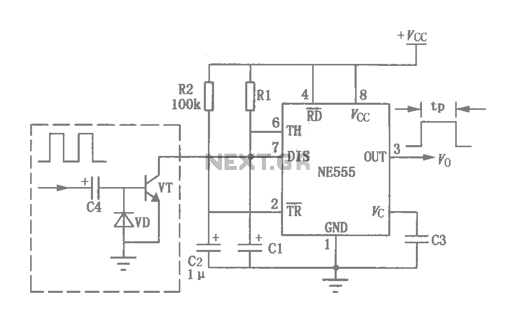
Menci alarm produced schematic circuit diagram

The alarm circuit is designed to detect the presence of a magnet and to signal an alert when the magnet is removed. The circuit begins with a power switch (SW1), which activates the entire system. Upon activation, the circuit enters a standby mode until a magnet is detected. The presence of the magnet influences a spring mechanism that connects dynamic and static switches, effectively closing the circuit and signaling a warning state.
When the magnet is removed, the spring mechanism reverts to its original position, which opens the circuit. This action sends a signal to the integrated circuit (IC1), which is responsible for processing the alarm signal. The timing resistor (R1) plays a crucial role in generating an audio signal within the circuit. This audio signal is then amplified by a transistor (VT1), ensuring that the output is strong enough to drive an alarm buzzer.
The use of a boost inductor is essential in this design, as it transforms the amplified audio signal into a high-voltage signal, which is necessary for operating the buzzer effectively. This results in a loud alarm sound that can alert individuals in the vicinity. Overall, the circuit is a straightforward yet effective design for an alarm system that leverages magnetic detection and audio amplification to provide an audible alert.The alarm circuit shown: alt="Menci alarm produced schematic circuit diagram"> Turn the power switch SW1, alarm electrical work. When the magnet is brought near the spring, the spring field magnet attracted to the magnet side, dynamic and static switch segment is turned on, the system is in warning status. When the magnet is removed after the spring loses magnetic field, back to the original position, then static and dynamic contacts open, starting the police, IC1 receives an alarm signal, the timing resistor R1, the internally generated audio signal, the signal output end, fed VT1, power amplification, the audio signal amplified by the boost inductor coupled into a high voltage audio signal to drive the buzzer loud alarm signal.
Related Circuits
This circuit was originally a type of power-delay control circuit, where the delay time is determined by the timing elements R1 and C1. Additionally, with the inclusion of a "watchdog" circuit, it can be utilized as a monitoring circuit...
This circuit is intended for precision centigrade temperature measurement, with a transmitter section converting to frequency the sensor's output voltage, which is proportional to the measured temperature. The output frequency bursts are conveyed into the mains supply cables. The...
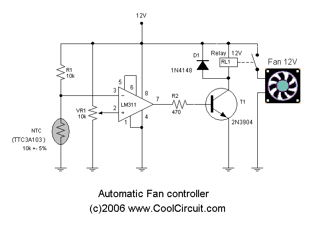
Automatic fan control circuit. This circuit turns a 12V DC fan or CPU fan on or off based on temperature readings. The temperature can be adjusted using VR1. The automatic fan control circuit operates by monitoring the temperature of...
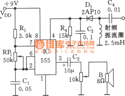
As shown in the figure, the 555 timer, resistors R1, RP1, and capacitor C1 form a controlled audio oscillator. The frequency of the oscillator is given by the formula f = 1.44 / ((R1 + 2 * RP1) *...
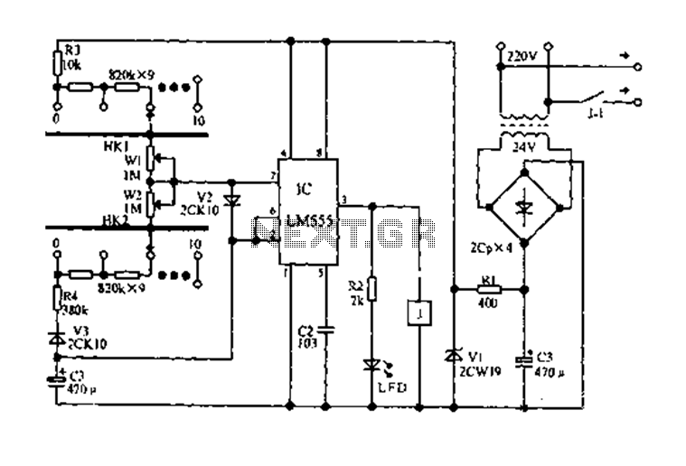
The circuit diagram for an electric start and stop timer is illustrated in the following cycle. It utilizes the LM555 integrated circuit configured as an adjustable duty cycle multivibrator. The circuit includes components C3, KH1, W1, KH2, and W2,...
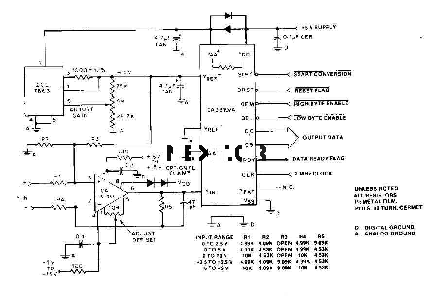
The BiMOS CA3140 operational amplifier offers excellent orientation capabilities for high bandwidth signal inputs and can swiftly adjust the energy output at its terminal CA33IO WINE. The CA3140 can also operate close to the negative supply rail. If the...