
Bus Description RS644 LVDS

The described circuit utilizes Low-Voltage Differential Signaling (LVDS) technology, which is characterized by its ability to transmit data at high speeds while maintaining low power consumption. The output voltage swing of 350 mV is specifically designed to ensure signal integrity over the specified distances and load conditions. This is crucial in applications where high data rates are essential, such as in high-speed data communication systems.
The choice of cable type is significant, as it directly affects the transmission distance and data rate capabilities. CAT3 and CAT5 cables are commonly used in networking applications, with CAT3 supporting shorter distances and lower data rates, while CAT5 is suitable for higher performance needs. The use of ribbon cables for sub-meter distances is advantageous in compact electronic designs where space constraints are a consideration.
The specification under IEEE 1596 provides a standardized framework for implementing LVDS, ensuring compatibility and performance across various devices and applications. The distinction between EIA-644 LVDS and other high-speed differential signaling technologies is critical for engineers to avoid misapplication of components and to ensure that the correct signaling methods are employed for specific requirements.
M-LVDS, or Multipoint LVDS, expands the application of LVDS technology by allowing for multiple devices to be connected on a single bus while maintaining signal integrity. The ability to extend the common-mode range to ±2 V is particularly beneficial in environments with significant electrical noise, enhancing the reliability of data transmission.
The design incorporates a 100-ohm termination resistor at the receiver, which minimizes reflections and ensures proper impedance matching. The inclusion of failsafe biasing within the receiver circuitry is an innovative feature that simplifies circuit design by negating the need for additional pull-up or pull-down resistors. This design consideration is particularly important in ensuring that the bus remains in a defined state when no active drivers are present, which is crucial for maintaining system stability and preventing erroneous data transmission.
Overall, this circuit design exemplifies the principles of modern high-speed data communication, leveraging LVDS technology to achieve efficient and reliable performance in a variety of electronic applications.Designed with an output voltage swing of 350mV at better then 400Mbps into a 100 ohm load, across a distance of about 10 meters. LVDS is only an Electrical spec - to be referenced by other specifications, it may be used with either a cable or PWB design.
The type of cable determines cable length; Category 3 (CAT3) for 10m in length, CAT5 for longe r runs (~20 meters @ 100Mbps, ~50 meters @ 50Mbps, ~100 meters @ 10Mbps). Ribbon cable may be used for sub meter runs. Also listed under IEEE 1596. 3. EIA-644 [LVDS] should not be confused with other (higher speed) Low-Voltage Differential circuits; ECL, PECL, LVPECL, or CML, all of which also use the term LVDS. M-LVDS Multipoint LVDS [EIA-899], Addresses double terminated bus configurations also extends the common-mode range to +/-2 V.
11mA drive at 500Mbps max, 200/300Mbps typical for Multi-point LVDS uses a single 100 ohm termination resistor at the Receiver side of the bus. The Receiver provides failsafe bias so Pull-up/down resistors are not required. Normally required once the system has reached it`s quiescent state, when no drivers are driving the bus.
Only one end of the bus requires the resistor network. 🔗 External reference
Related Circuits
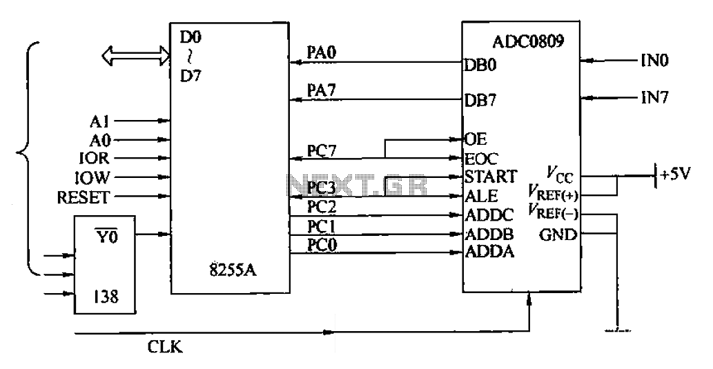
The ADC0809 is an 8-channel analog switch integrated with an 8-bit successive approximation analog-to-digital (A/D) converter. It supports the selection of eight input channels through address latch and encoder channel selection signals ADDA, ADDB, and ADDC. The address latch...
This article was previously published, but the intention is to spread the idea further, potentially inspiring new concepts. An improved version was being developed using an ULN2803A instead of multiple BC547B transistors and optional Zener diodes to ensure that...
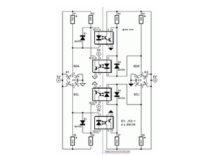
When the SDA (Serial Data) lines on both the left and right lines are high (logic level 1), the circuit remains in a quiescent state, and the optoisolators IC1 and IC2 are not activated. In this circuit, the Serial...
If a complete circuit is needed, there are thousands of these circuits available in the designs. Some of them can be provided easily, but further communication is required. The request indicates a need for a comprehensive circuit design, which may...
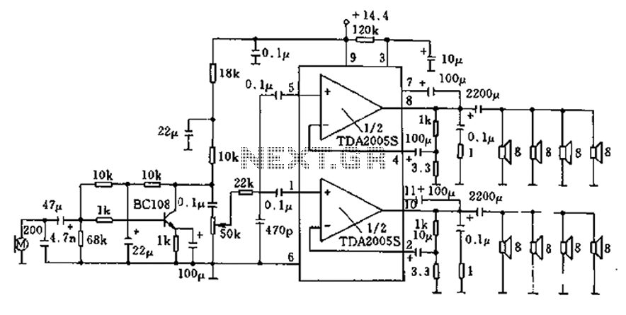
20W bus radio and megaphone circuit utilizing the TDA2005S double low-frequency power amplifier integrated circuit design. The front end can be connected to either a microphone input or a low-frequency radio output voltage amplification stage. Each TDA2005S provides 10W...
How the circuit works. The circuit comprises a non-inverting amplifier with a final output buffer stage or voltage follower for impedance matching. The described circuit functions as a non-inverting amplifier, which is designed to amplify an input voltage while maintaining...