
Bus Interface Description RS422

EIA/TIA-422 is a standard that defines a robust and efficient method for data communication using a differential signaling technique. This approach minimizes electromagnetic interference and allows for longer cable lengths compared to single-ended signaling. The architecture supports a unidirectional data flow from a driver to multiple receivers, making it ideal for applications where a single source needs to communicate with multiple endpoints, such as in industrial control systems or telemetry applications.
The maximum data signaling rate of 200 kbps at a cable length of 500 meters indicates the versatility of RS-422 in various environments. The specification for grounding and the use of resistors for idle-line failsafe ensures that the system remains stable and reliable, even when no active communication is occurring. The inclusion of ESD protection components, such as TransZorb diodes and steering diodes, enhances the circuit's resilience against voltage spikes, which is crucial in industrial settings where electrical noise is prevalent.
The recommendation to use 24 AWG twisted pair copper wire with a capacitance of 16 pF/ft is significant for maintaining signal integrity over longer distances. The design considerations regarding termination resistors and their values are essential for optimizing the performance of the network, ensuring that reflections are minimized and signal quality is maintained.
Overall, EIA/TIA-422 provides a comprehensive framework for differential signaling in data communications, ensuring compatibility with various devices and systems while promoting reliability and efficiency in data transmission.EIA/TIA-422 defines a Balanced (differential) interface; specifying a single, unidirectional driver with multiple receivers (up to 32). RS-422 will support Point-to-Point, and Multi-Drop circuits, but not Multi-Point [ EIA485 ]. EIA-485 devices may be used in 422 circuits, but EIA-422 may not be used in 485 circuits (because of the lack of an Enab
le line). EIA422 is the differential "brother" to EIA423. One application note indicated that the combination of cable length (in meters) and data signaling rate (in bps) for RS422 should not exceed 108. The example provided a maximum speed of 200kbps with a maximum cable length of 500 meter [500 x 200, 000].
An EIA-422 driver can support up to 10 loads, at 4K W per load. Circuit grounding is not shown in either of the RS422 or RS485 circuits. However, the circuits should be grounded. The drivers and receivers should be connected directly to circuit ground. The circuit ground should be connected to chassis ground via a 100 ohm resistor. If the far-end circuit resides in another chassis, then the two circuit grounds should be connected together via a 100 ohm resistor at each end. For additional ESD protection TransZorb [back-to-back] diodes may be added between the input/output lines and ground.
This link provides part numbers and pin-outs for a DIP Package TVS Array. Steering Diodes [1N6101] may also be added to the input lines to protect the RS422 receivers. One diode between the I/O and Vcc, and another between the I/O and ground. Three different diode configurations and part numbers are shown on the DIP Package Diode Array page. Cabling is not specified in RS422 or RS485, but a rule of thumb is listed above for 24 AWG twisted pair copper wire with 16pF/ft. Refer to 24AWG Attenuation vs Frequency Chart. The Pullup/Down Resistors (Idle-line failsafe) are used to keep the +/- inputs of the Receiver(s) inputs at a minimum of 200mV differential.
The resistors are normally required once the system has reached it`s quiescent state, when no drivers are driving the bus. Only one end of the bus requires the resistor network. The resistor values are dictated by four factors: The input impedance of the receivers (between 5K and 90K ~ check the data sheet), the number of loads, the termination resistance 60 ohms (120 ohms per side), and the required (turn-on) current of the receivers.
The nearest 5% standard value is 680W placed between both the `A` line and +V connection and the `B` line and the GND connection will produce < 3. 5 mA (turn-on current} RS422 and RS485 do not define cabling or connector information. RS449 and RS530 [listed below] are two common cabling specifications which are used with the RS422/485 electrical standards.
Use 24 AWG twisted pair copper wire with 16pF/ft for cables. Maximum cable length is determined by the combination of cable length (in meters) and data signaling rate (in bps). RS422 should not exceed 108 for length x bps. The example provided a maximum speed of 200kbps with a maximum cable length of 500 meter [500 x 200, 000].
Charts of Cable Data Rate vs Cable Length. EIA/TIA-449 ; General Purpose 37-Position Interface for Data terminal Equipment and Data Circuit-Terminating Equipment Employing Serial binary Data Interchange TIA-449 is a serial mechanical interface standard for transmission of balanced and unbalanced signals between a variety of higher-end computer, media, and multimedia peripherals. EIA-449 allows a maximum data rate of 10 Mbit/s and uses a 37-pin or 9-pin connector. EIA/TIA-530 ; High Speed 25-Position Interface for Data Terminal Equipment and Data Circuit-Terminating Equipment, Including Alternative 26-Position Connector EIA-530 is a replacement for EIA-449 that uses a DB-25 ( EIA-232-D ) connector instead of a 37-pin connector, while keeping the most important electrical signals intact.
EIA-530 is to be used in conjunction with EIA-422-A. Normally EIA422 and 423 systems may no 🔗 External reference
Related Circuits
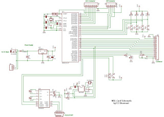
This is a home-made kit featuring the ATmega32 microcontroller interface. The ATmega32 controller is equipped with various features, including 32kB of in-system programmable flash memory, 1KB of EEPROM, 2KB of SRAM, a 10-bit ADC with 8 channels, an SPI...
The circuit schematic of the UDC consists solely of dispersive components. Two low-frequency series LC resonators, with equal inductances (LA=LB) and capacitances (CA=CB), are connected to two input semi-infinite transmission lines, designated as A and B. These resonators are...
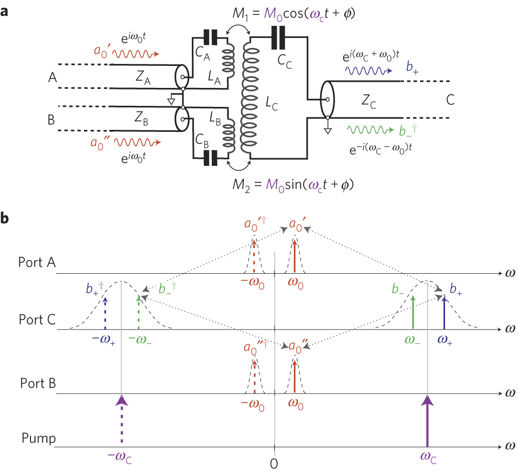
Here is an inexpensive way to get slow-moving analog data directly into a spreadsheet on your computer! A simple circuit connects to a serial port and a short Qbasic program gathers and saves 12 bit data to a file....
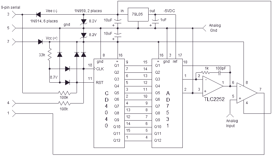
This design is intended for PC soundcards. For an interface suitable for a Mac, please refer to another page. For computers and PCs lacking a soundcard, Harmony Central's interface page may be helpful. The design has been constructed successfully,...
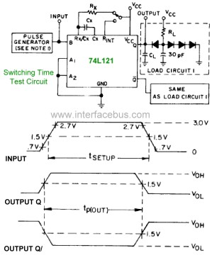
The pinout diagram for the 74L121 and 74L122 integrated circuits (ICs) is applicable to any style of 74xx121 or 74xx122 dual in-line package (DIP) chip, although the timing graphs are only relevant for the indicated TTL families. The 74121...

This joystick model was introduced by IBM alongside their first IBM PC computer. It is a basic analog joystick featuring two buttons. The original joystick interface included a circuit for connecting two joysticks but only had one joystick connector....