
PC joystick interface

Game port 201h byte:
_ | 7 | 6 | 5 | 4 | 3 | 2 | 1 | 0 |
| | but4 | but3 | but2 | but1 | stk4 | stk3 | stk2 | stk1 |
|_|_|_|_|_|_|_|_|
The four most significant bits indicate the state of the joystick buttons, while the four least significant bits represent the states of the multivibrators used to measure the resistance values of the joystick position potentiometers. A more detailed description of the bit meanings is as follows:
7 6 5 4 3 2 1 0
*. . . . . . . Button B2 (pin 14), 0=closed, 1=open (default).
*. . . . . . Button B1 (pin 10), 0=closed, 1=open (default).
. *. . . . . Button A2 (pin 7), 0=closed, 1=open (default).
The joystick's operational design relies on the interaction between the potentiometers and the interface card, which processes the analog signals generated by the joystick's movements. The simplicity of the design allows for effective integration with early IBM PC systems, while the evolution of joystick technology has led to improved capabilities and features in modern gaming peripherals. The analog nature of the joystick allows for smooth and continuous input, making it suitable for a variety of applications, including gaming and simulation. The implementation of dedicated joystick cards and the evolution of software routines have addressed many of the timing and detection issues that arose with increasing computer speeds, ensuring reliable performance across a range of hardware configurations.This joystick model was presented by IBM together with their first IBM PC computer. The joystick is just a basic analogue joystick with two buttons. The original joystick interface had circuit for connecting two joysticks, but had only one joystick connector. A special Y-cable was needed if there was need for two joysticks at the same time. Later time some manufacturers put two connectors to their interface card and some card manufacturers implemented only one joystick input. Fortunately most of the card nowadays have option for two joysticks like the original IBM joystick card.
The joystick interface card was designed to be as simple and cheap as possible. The card consisted only of bus interface electronics and four monostable multivibrators (all in on 558 chip). Those monostable multivibrators were simple timer circuits which put out a pulse with width directly proportional to the joystick resistance value.
The pulse width was then measured using software loop. This has caused anormous amounts of problems to game programmers when computers have become faster and faster all the time. On faster machines, the joystick routine in the software does not read the joystick signal properly resulting in a timing problems.
Some dedicated joystick cards are designed to vary the joystick signal so the software can properly detect the joystick and process the data. The joystick consists of two potentiometers with variable resistance value between 0 Ohm and 100 kohm (in some joysticks up to 150 kohm).
The potentiometer resistances have the minimum values when the joystick is at the top left position. One end of the potentiometer is connected to +5V pin and the center pin is connected top the analogue input of the joystick. The other end of the potentiometer is left not connected to anywhere. There are two commonly used ways how PC analogue joystick stick mechanism is constructed. Some joystick convert the stick position to linear motion, whcih then changes the position of the slider in about 100 kohm linear potentiometer.
More popular construction is to use normal axial potentiometers and the joystick movement directly turns those potentiometers. Some joystick used special 100 kohm potentiometer which can only turn that 60. 90 degrees which joytick can turn. The more common construction is to use the standard 470 kohm (lin) 270 degree potentiomer and use about one fourth of the scale from the beginning (in this way getting 0.
120 kohm value range). Usually those potentiometers are normal carbon slider potentimeters which do not last long in intense gaming. The joystick port is a very simple 8 bit I/0 card which resides in ISA bus I/O address 201h. The CPU can read and write to the joystick port I/O address 201h. Writing to that address starts joystick postition measurement. Joystick interface only uses the signal that somebody is writing to the I/O address to reset the multivibrators in the card.
The data value is not stored anywhere, so it is really same what value is written to this address. When you read one byte from I/O addess 201h, you get the status information of the joystick interface. The following table will show how the bits are mapped in the value you get. Game port 201h byte: _ | 7 | 6 | 5 | 4 | 3 | 2 | 1 | 0 | | but4 | but3 | but2 | but1 | stk4 | stk3 | stk2 | stk1 | |_|_|_|_|_|_|_|_| The four most significant bits tell you the state of the joystick buttons.
Four least significant bits tell the state of the multivibrators which are used for measuring the resistance value of the joytick position potentiometers. More accurate description of the bit meanings can be found at the table below: 7 6 5 4 3 2 1 0 *. . . . . . . Button B2 (pin 14), 0=closed, 1=open (default). *. . . . . . Button B1 (pin 10), 0=closed, 1=open (default). . *. . . . . Button A2 (pin 7), 0=closed, 1=open (default). . . * 🔗 External reference
Related Circuits
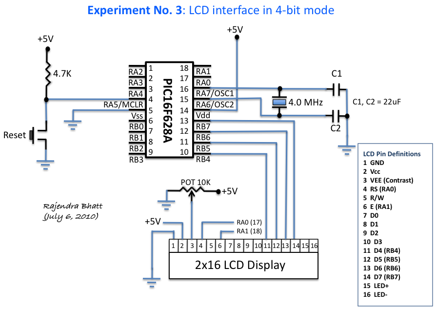
An HD44780 Character LCD is a liquid crystal display (LCD) device designed for interfacing with embedded systems. These screens are available in various configurations, including 8x1 (one row of eight characters), 16x2, and 20x4. The most commonly produced configuration...
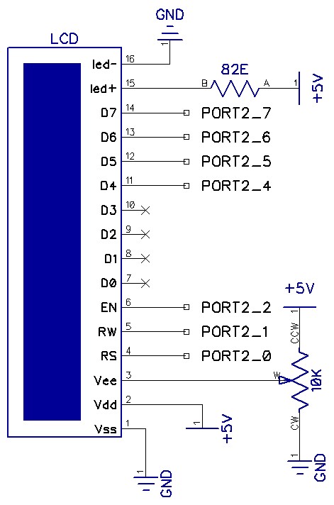
The circuit utilizes a total of seven pins from the microcontroller's GPIO. Consequently, the LCD module requires only one port out of four available. The EN line, known as "Enable," is a control line that indicates to the LCD...
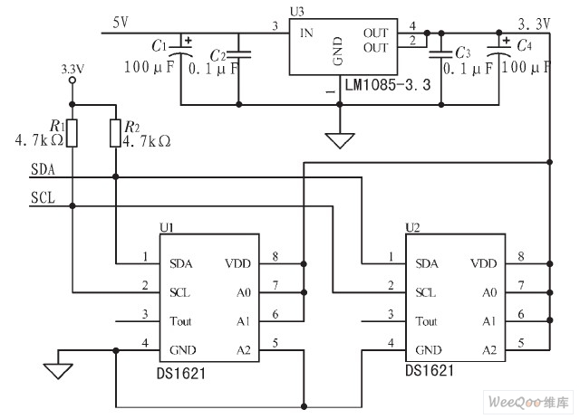
The IIC bus line is a type of communication protocol that facilitates the transmission of data between devices. It is characterized by its simplicity in construction and wiring, making it suitable for various high-performance applications. The operating system, particularly...
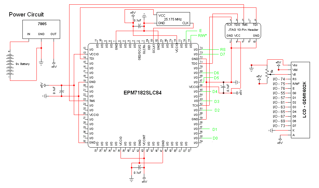
The schematic for this project is a modified version of the CPLD development board schematic. Several new components have been added for this project, and the completed schematic is presented below. The primary components in the schematic include the...
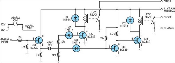
Some inexpensive car alarms lack a connection for the central locking system. However, in most cases, it should be possible to identify a point within the alarm circuit. Many budget-friendly car alarm systems are designed with basic functionalities, often omitting...
This self powered interface circuit electrically isolates the TxD and RxD lines from the PC serial port and protects the PC from direct connection to hazardous voltages. The isolator is intended to provide electrical isolation between a computer and...