
Butler Oscillator
The Butler crystal oscillator is a versatile circuit that can be configured for various frequencies, utilizing both fundamental and overtone modes of operation. The common base configuration, while sometimes criticized, can yield excellent performance when properly managed. The design considerations for this oscillator include selecting appropriate inductance and capacitance values tailored to the desired frequency of operation.
In practice, the choice of components such as low-noise JFETs, capacitors, and inductors is crucial. The J310 FET, known for its low noise figure, is particularly suited for VHF applications where signal integrity is paramount. The use of ferrite beads and resistors in the feedback loop helps mitigate unwanted UHF oscillations, ensuring stability and reducing spurious emissions.
The tuning process involves careful adjustment of the inductor and trimmer capacitors to achieve a clean sine wave output. The inductance can be fine-tuned by altering the physical configuration of the inductor, which may involve adjusting the number of turns or the spacing between coils. This iterative process often requires the use of an oscilloscope to visualize the waveform and make necessary adjustments.
The design of the Butler oscillator can be further optimized by analyzing the reactance values derived from professional schematics. By calculating the necessary L and C values based on these reactances, one can establish a solid foundation for experimentation. The ability to modify these values in response to testing results is essential for achieving the desired performance characteristics.
Overall, the Butler crystal oscillator remains a valuable tool for engineers and hobbyists alike, offering a balance of simplicity and effectiveness in generating stable frequencies across the VHF spectrum.My first tasks involved buying some VHF parts + exploring the Butler crystal oscillator. Specifically, I`ll cover my experiences with the common base version of the Butler oscillator. Like HF, the VHF knowledge base contains ever-present lore. Consider the Butler oscillator ” I have read arguments stating that the emitter follower version of the Butler oscillattor is vastly superior to the common base version because the latter is prone to UHF and other spurs. These comments seem to have originated from a good book entitled Crystal Oscillator Circuits. While examining the schematics of professional/world class gear using a Butler, the common base version clearly dominates. Spectrum analysis and other measurements indicate that when common UHF oscillation management techniques are applied, common base Butler crystal oscillators work well.
Suppressing UHF oscillations with ferrite beads (and small value resistors), feedback, neutralization, limiting gain, etcetera are routine practices for us experimenters applying active devices that have strong gain into UHF on up. This is vanilla, or matter-of-fact construction for us; no worries. While fun and often convenient, lore ultimately stifles our progress. Increasingly, I`m adopting the philosophy of Bob, K3NHI; "TMITK" ” to measure is to know. Consider, too, you have to know what to measure and possess the required gear. For JFETs, the J310 in TO-92 and SMT will remain my workhorse FET part along with a couple of other low noise JFETs and 2-gate MOSFETs.
At VHF, the noise figure in a receiver chain is established by the first amplifier so a low noise preamp ranks important. A collection of 100 volt NP0 capacitors ranging from 1 pF to 22 pF were added along with some chip and SMT caps as low as 0.
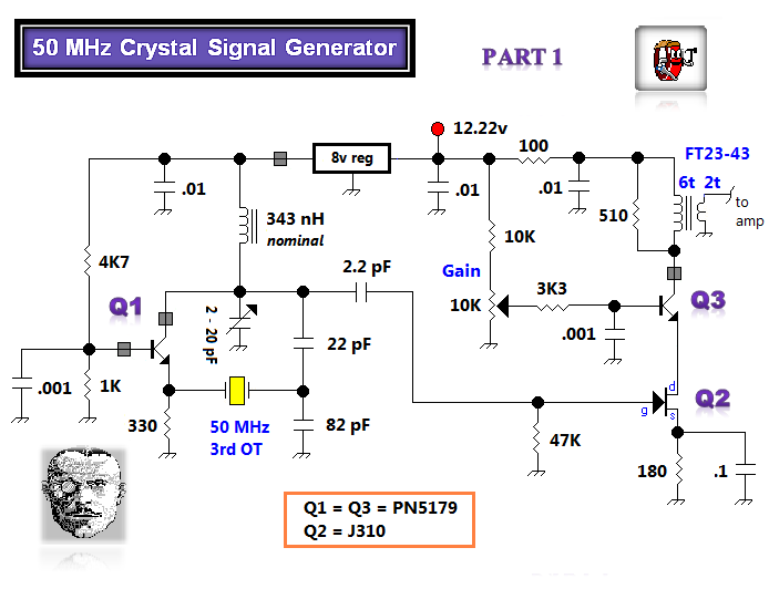
5 pF. You might need a few air trimmer capacitors with a minimum capacitance ~ 2 pf ” I applied 2 - 20 pF trimmer capacitors in most of the circuits that follow. Long ago, I pulled a crystal marked 70. 00000 MHz from a Drake Transmitter. I keep a fundamental oscillator based upon EMRFD Figure 4. 23 on hand and verifed the fundamental frrequency at 23. 3 MHz. Above ” A Butler oscillator arranged for output at the fundamental crystal frequency. While commonly arranged as an overtone oscillator, the Butler is a good oscillator for any application.
Consider, for example, EMRFD Figure 7. 32. Wes applied the Butler at a 14 MHz fundamental because he wanted the lowest phase noise and IMD prone signal source possible. Tellingly, his buffer circuitry also conforms to this high standard. My initial waveform looked distorted and prompted a solution. My experience yields that the L value needs to be adjusted for the best looking waveform in the Butler circuit.
The inductor wire, wrapped around a T30-6 toroid was either scrunched to increase the inductance, or expanded to decrease the L while re-peaking the trimmer cap. Eventually, with patience, a beautiful sine wave emerged on my `scope. I removed and measured the L with an ADE inductance meter. Consider all of my reported inductance values as nominal ” gentle expansion or contraction of the inductor coils might be required to get an agreeable sine wave.
Above ” A template (of sorts) for calculating Butler capacitor and coil values. The concept, rather than the absolute value matters most. I examined some well-designed Butler oscillators from professional equipment and determined their average XL and XC values. From the reactances shown, calculate the L and C values for the overtone frequency of interest with the 2 formulas in orange boxes.
Remember these XL or XC values just serve as starting values for experiments. Fine tuning of the capacitor and inductor values might be required since factors including buffer input resistance +/- reactances, the overtone frequency and/or your breadboard 🔗 External reference
Related Circuits
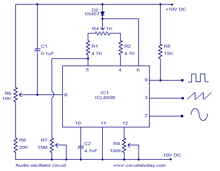
ICL8038-based audio oscillator circuit. Simultaneous sine, triangle, and square waveforms. Dual supply operation. Covers the full audio frequency range. The ICL8038 is a precision waveform generator integrated circuit that can produce sine, triangle, and square waveforms simultaneously. This versatility makes...

The circuit operates as a unijunction transistor relaxation oscillator. The base of the lower PNP transistor is biased at approximately half of the supply voltage. As the 100pF capacitor charges through the 1GΩ resistor, the base of the upper...
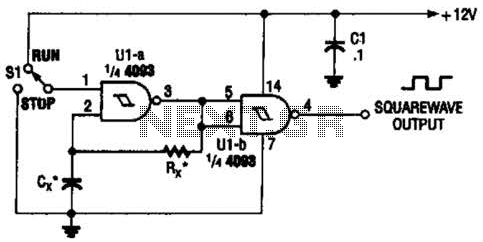
Two gates of the Quad 4093 are utilized to create an oscillator. The resistor (R) can range from approximately 5 kΩ to around 10 kΩ. The capacitor (Cx) can vary from about 10 pF to higher values, with the...
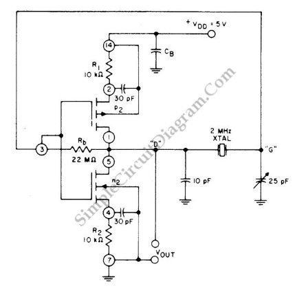
This circuit is a 2 MHz crystal oscillator utilizing a CMOS transistor pair. It is particularly suitable for applications in digital watches and clocks due to its low power consumption. The oscillator is constructed by connecting a CMOS transistor...
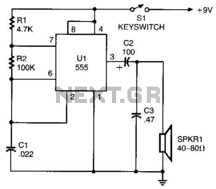
A 555 timer configured as an astable multivibrator is used in this circuit to generate an audio note. The capacitance value can be changed to vary the audio note as desired. The circuit utilizes a 555 timer IC, which...

This circuit includes an amplifier designed to deliver +10 dBm to an SBL series (Mini-Circuits) or a similar type of doubly-balanced mixer assembly. The circuit parameters are specified for 80 to 90 MHz crystals, although the values of the...
Warning: include(partials/cookie-banner.php): Failed to open stream: Permission denied in /var/www/html/nextgr/view-circuit.php on line 713
Warning: include(): Failed opening 'partials/cookie-banner.php' for inclusion (include_path='.:/usr/share/php') in /var/www/html/nextgr/view-circuit.php on line 713