
c programming tutorial setup
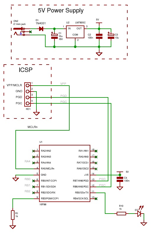
The described setup involves several critical components and steps for programming a PIC microcontroller. The initial focus is on ensuring that the Low Voltage Programming (LVP) mode is disabled, which is essential for the effective use of the microcontroller's pins. The use of a USB to RS232 converter facilitates communication between the microcontroller and a PC, enabling programming and data transfer. The flashing LED serves as a simple verification method to confirm that the microcontroller is operational following programming.
The internal features of the microcontroller, such as the oscillator and reset circuit, are significant advantages as they reduce the number of external components required, thereby simplifying the circuit design. The use of software like ICPROG is crucial for generating the correct programming signals, and proper installation and configuration of this software are necessary for successful programming. By ensuring the correct setup of hardware interfaces and software parameters, the microcontroller can be effectively programmed and utilized for various applications, paving the way for more complex projects in the field of electronics.For the other components you should have most of the stuff lying around if you have doneany type of electronics except for the programmer, RS232 chip and PIC. For getting information out of the project and into the PC a USB to RS232 is needed and this can also be bought on ebay.
The first thing you need to do is down load the compiler : Click Here . Download theexecutable to your computer, double click it and follow the instructions. R1stops the part entering the wrong programming mode (LVP mode). LVP mode is the default mode (Low Volt Programming) and is always enabled for new parts but it makes the pin unusable for anything else. Since there are not many pins in this particular part the first task is to disable LVP mode. You can do this by programming the part with the first program which has turned off the LVP fuse and at the same time it flashes the LED so once the part is programmed you can see that it`s working.
Note: Later diagrams may not show R1 as it is only important when 1st programming the part (if you ensure that the LVP control is always set to off in the compiler project edit control panel - see videos for more information on that). Once LVP isprogrammed off then the PGM pin becomes a `normal` pin i. e. you can treat it as normal I/O and use it just like any other programmable I/O pin. Note:I use 7zip - just do a google search for `7zip` if you don`t have an unzip program which is free and integrates into the windows shell - meaning you can right click in explorer and directly zip/unzip files.
Unzip the file `prog00-16F88-intro. zip` in the pic-c-course directory. It will create a directory c:pic-c-courseprog00-16F88-intro in which will be a hex file. For this C programming tutorial you should have installed ICPROG so start that program up now. Setup the hardware interfaces for your programmer using the options menu. Note: You can set the I/O delay to zero (tested on my parallel port programmer) - this will program the device slightly faster. Also if you use XP you`ll need to select the Windows API interface (in the above box). You should now have a circuit with a flashing LED - this is the equivalent of the "hello World" program you usually find in the start of C courses but because the microcontroller is only concerned with I/O ports there is no way of displaying a message yet.
The internal oscillator is running at 4MHz and saves you using an external crystal or RC network. Similarly the reset circuit is also internal. Both these features save pins as what was once a dedicated reset pin can now be used as an I/O pin. Again using the internal oscillator saves two pins for use as I/O pins. I started out by building a parallel port interafce - and it works fine - do check on this website for details of that parallel port programmer as you will need to inculde the transmission line termination impedance to make it work over long cables reliably). Download and install ICPROG which is PC software that generates the correct serial ICSP signals to program your PIC chip.
You can use it either on a parallel port, serial port or USB port with a USB to serial adapter - ( USB <-> Serial untested). You should setup the environment variable to icprog. exe so that it can be called from anywhere but if you don`t you can still start icprog by double clicking icprog.
exe in its installation directory. The installation location is up to you but you should put it into a directory that is in the current path so that windows can find it or add the directory (where you put ICPROG) to the system path environment variable. Unfortunately setting up the windows path is different for every windows installation from Windows 95 to XP so you will need to find the exact details for your operating system.
Windows 95 uses autoexec. bat and config. sys. For XP you can set the path from Start -> Control panel -> System -> Advanced (tab) -> Environment variables. You can set the pa 🔗 External reference
Related Circuits
It is now possible to program microcontrollers at home with a cost-effective AT89S51 series microcontroller burning IC kit. The AT89Sxx series ICs feature an inbuilt ISP (In-System Programming) module, allowing for easy programming of the microcontroller. This document presents...
This page outlines how to create a simple theft deterrent that can be quite effective. The concept involves using a flashing red LED to indicate that the vehicle is protected. This device serves to safeguard the car from potential...
Since the 1970s, a remarkable era in technology, amplifiers have been available in integrated chip form, eliminating the need to construct them from numerous discrete transistors. This video provides an overview of operational amplifiers (op amps) and includes an...
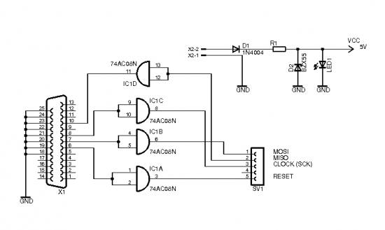
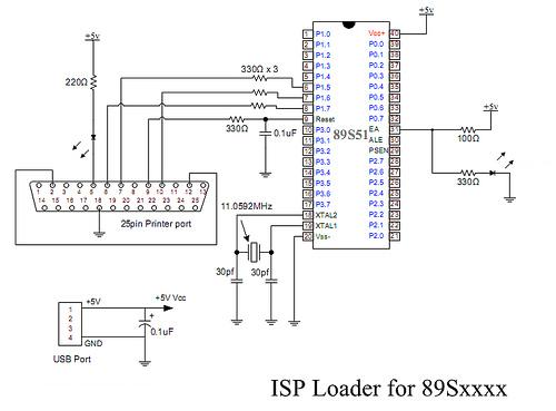
The brain of the robot is composed of an Atmel Tiny2313 microcontroller. This MCU features In-System Programming, allowing programming of its memory using a low-cost programmer. A simple programmer connects to the parallel port and is described in the...
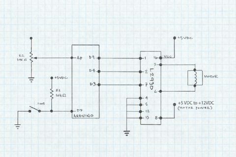
The L293D H-Bridge is utilized to operate a 12V DC motor with an Arduino. This H-Bridge facilitates the interfacing of the motor, which requires significantly more current and voltage than the output pins can provide. With minimal connections, it...

A DC motor operates by converting electrical power into mechanical work. This process involves passing current through a coil, which generates a magnetic field that causes the motor to spin. One method to adjust the speed of a DC...
Warning: include(partials/cookie-banner.php): Failed to open stream: Permission denied in /var/www/html/nextgr/view-circuit.php on line 713
Warning: include(): Failed opening 'partials/cookie-banner.php' for inclusion (include_path='.:/usr/share/php') in /var/www/html/nextgr/view-circuit.php on line 713