
DC Motor Tutorial

A DC motor is an electromechanical device that converts electrical energy into mechanical energy through the interaction of magnetic fields. The fundamental operation involves a rotating coil situated within a magnetic field, where the application of electric current induces movement. The speed of a DC motor can be effectively controlled by varying the voltage supplied to the coil, which can be accomplished using PWM techniques.
PWM involves switching the power supplied to the motor on and off at a high frequency, effectively controlling the average voltage and current reaching the motor. By adjusting the duty cycle of the PWM signal, the average voltage can be increased or decreased, thus providing a means to fine-tune the motor's speed.
In practical applications, a microcontroller typically generates the PWM signal. However, due to the limited current output capabilities of microcontrollers, an intermediary component such as a buffer or an H-bridge driver is necessary to handle the higher current requirements of the motor. The H-bridge configuration allows for the reversal of motor direction, providing flexibility in motor control.
The L298 driver is a common choice for driving DC motors as it can control two motors independently and can handle the necessary current and voltage levels. In a typical setup, the microcontroller outputs PWM signals to the L298 driver, which in turn regulates the power supplied to the motor. The schematic for this configuration would include connections from the microcontroller to the input pins of the L298, as well as connections to the motor terminals, ensuring that the system can operate in both forward and reverse directions while maintaining precise speed control.
This approach not only enhances the control of the motor but also protects the microcontroller from potential damage due to excessive current draw. Properly designed, this system can achieve efficient and reliable performance in various applications requiring precise motor control.A DC motor worksby converting electricpower into mechanical work. This is accomplished by forcing current through a coil and producing a magnetic field that spins the motor. One technique to vary the speed of a DC motor is by varying the voltage on the coil. To do this with a microcontroller, PWM output must be used so that the Duty cycle can be c hanged and automatically the average voltage output will be changed too. Consequently the speed ofthe motorwill be changed. This can be seen in the figure below: To drivea dc motor from amicro-controller, there must be a buffer or an H-bridgedriverso thatthe motorwill not be driven directly by the micro because the current needed is not sufficient. The schematic below shows an example how to connectthe motorto be driven in both direction (foward and reverse) with an L298driverand connected to a microcontroler (using PWM to control the speed control).
🔗 External reference
Related Circuits
Electric motors have been widely used for motion control, and various types of motor controllers have been designed to provide variable speed drives for these motors. Electric motors are integral to numerous applications requiring precise motion control, ranging from industrial...
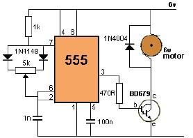
This project utilizes a 555 timer to control the speed of a 6-volt DC motor. Speed adjustment is achieved by rotating a 50 kΩ potentiometer either to the left or right. The circuit employs a 555 timer configured in astable...
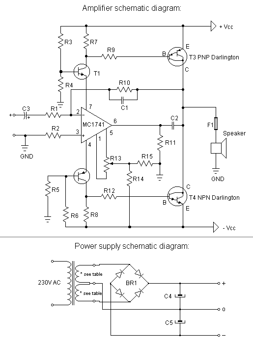
The first step is to measure the amplification factor of the end transistors (T3 and T4), known as the hfe. If their difference exceeds 30%, the amplifier will produce unclear sound. In this case, MJ3001 and MJ2501 transistors were...
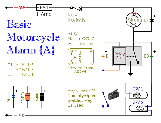
These are two easy-to-build relay-based alarms that can be used to protect motorcycles, among other applications. Using relays with 6-volt coils will safeguard a "Classic Bike." Both alarms are compact, with completed boards occupying approximately half a cubic inch...
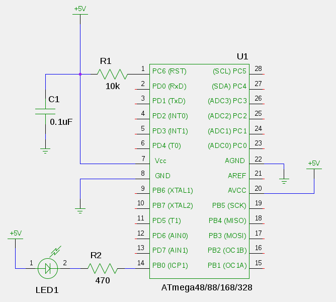
Blinking an LED is the introductory project for programming microcontrollers. It serves as an effective method to navigate the entire development process and verify the functionality of all tools. This chapter involves connecting a light-emitting diode (LED) to an...
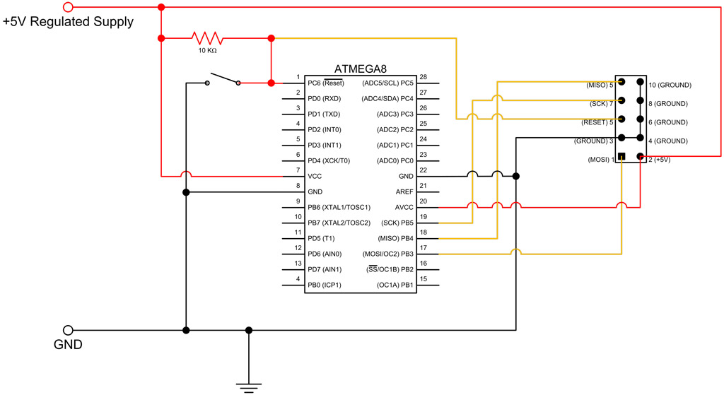
This tutorial continues from the ATmega8 Breadboard Circuit Part 1, where a small power supply was built on a breadboard. In this part, the ATmega8 microcontroller will be added along with an interface for programming. The first step is...