
Programming the microcontroller
The Atmel Tiny2313 microcontroller serves as a compact and efficient control unit for robotic applications, leveraging its In-System Programming capability to facilitate easy and cost-effective memory programming. The integration of a simple programmer using the 74HC08 IC exemplifies an economical approach to hardware design, allowing for direct connection to the parallel port without the need for a PCB. The design considerations, including cable length restrictions and alternative programming methods via PonyProg, reflect the challenges often encountered in embedded system development. The choice of AVR Studio as the development environment, complemented by the WinAVR toolset for C programming, provides a robust framework for developing complex control algorithms.
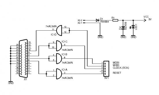
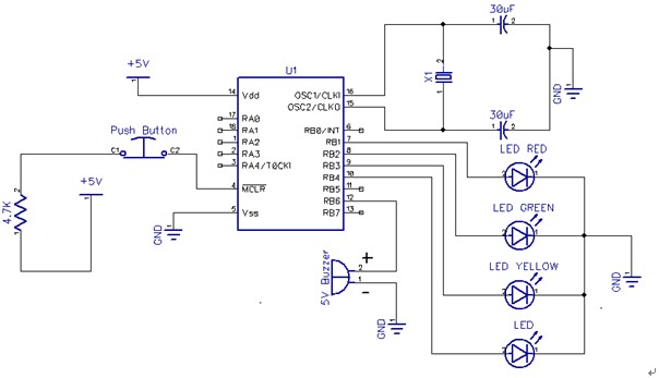
In the operational context of the robot, the implementation of state-based control through interrupts and sensor feedback mechanisms demonstrates a sophisticated approach to real-time system responsiveness. The architecture allows for seamless transitions between manual and autonomous control, with the main loop continually monitoring and executing actions based on sensor inputs. The PWM generation method, while initially relying on timer outputs, highlights the importance of resolution and performance in servo control applications. The design choices made in this project reflect a thoughtful balance between cost, functionality, and performance, ensuring the robot operates effectively within its intended environment.The brain of the robot is made of Atmel Tiny2313 microcontroller. This MCU has a cool feature called In-System Programming which can be used to program memories of the MCU with almost-no-cost programmer. I used simple programmer which connects to parallel port. It is described in [ 2 ] and its schematic is below. The 74HC08 integrated circuit, whi ch is the only part of this programmer besides the connector, costs about 50 cents. Everything can be built directly into the 25-pin LPT connector without any PCB. On the microcontroller side of the cable, I use pinhead female connector with my own layout as shown in fig. 4. 2. Note that the cable should not be longer than about 50 cm. If parallel port is not available on your computer, you can use PonyProg software [ 4 ] with interface for serial port.
The programming device is also very simple. Note that if you use laptop with USB to Serial converter PonyProg may run very slow (10 minutes for programming the memory) so this is not a good choice. I did not find any solution for this yet, but luckily my laptop has a parallel port and my old PC has both serial and parallel port.
The simplest solution would be to buy some commercial Atmel programmer for USB, such us ISP MK II, which can cost about $40. The program for the MCU is built in AVR Studio, which is free IDE provided by Atmel [ 5 ]. AVR studio allows writing programs in assembly language only, but there is free set of tools including C compiler called WinAVR [ 6 ] available.
WinAVR integrates into AVR studio seamlessly, so it is possible to write programs for the MCU in C. So to sum it all up, the program for microcontroller is written in C and built with WinAVR tools integrated into AVR studio. First, download and install AVR studio. Then install WinAVR and it will integrate into AVR studio automatically. Then download and open the project with source code for Krabos. In every pass through the loop one step is performed. What the step is depends on the state. For example, in Walk state one step is one complete set of movements of the servos which makes the robot do one step forward.
The state of the robot can be changed either by pressing the switch on control board or by a command from serial line. The switch can only toggle state between stopped and autonomous movement. When controlled from PC, a command arriving through serial line generates interrupt and interrupt handler routine changes the state of the robot according to this command.
The change is recognized by the main loop during the next pass, so it may take some time before the robot responds to the command. The bump sensors generate interrupt when activated (when robot touches an obstacle). The interrupt handlers only change state of the sensor in global variable (gLeftSensor or gRightSensor) and disable further interrupts from the sensor.
Main loop can respond in the next pass. If the robot is in autonomous mode it will stop and turn etc. If controlled from PC, it is responsibility of the PC software to check for sensors and respond accordingly. Software controlling the robot from PC can read the sensor state by sending Get Sensor State command to the robot.
The robot will send back information about the sensor (whether it is activated or not). PWM signal for servos can be generated using 2 timers available in the MCU (each timer has 2 PWM channels). This option was tried first and works fine. It is still available in the source code if you uncomment the PWM_VER1 directive in ServoDriver. C. However, using the timer-based PWM has some disadvantages because of which the current version of the software generates PWM in a different way and the PWM_VER1 directive is commented out.
The problem with native PWM generated by the timer is the resolution of the timer counter, which is only 8 bits. The period of the PWM is thus divided into 256 parts. The period should be 20 ms for the servo. The active level 🔗 External reference
Related Circuits
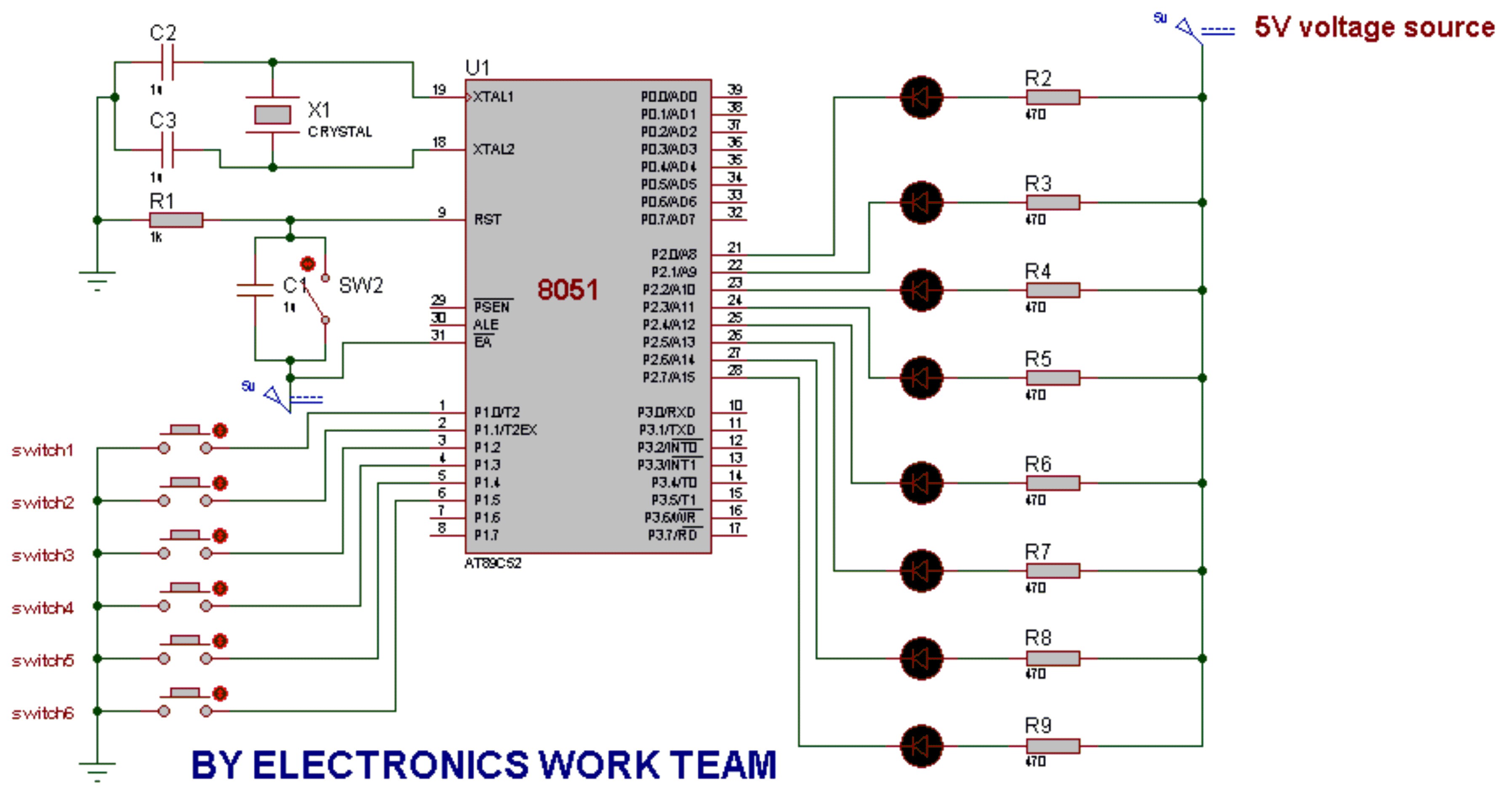
This post discusses the fundamental operation of the 8051 microcontroller using LEDs. The LEDs are connected to the P2 port, while six switches are connected to the P1 port of the 8051. By pressing various switches, the LEDs will...
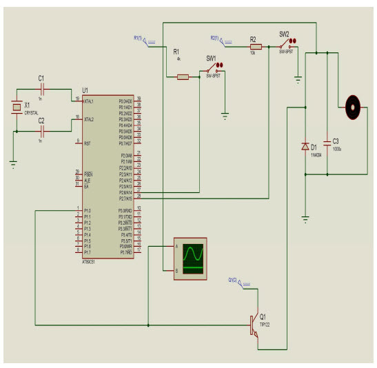
The objective of this project is to control the speed of a DC motor. The primary benefit of utilizing a DC motor is the ability to modify the Speed-Torque relationship to nearly any desired form. To facilitate speed control,...
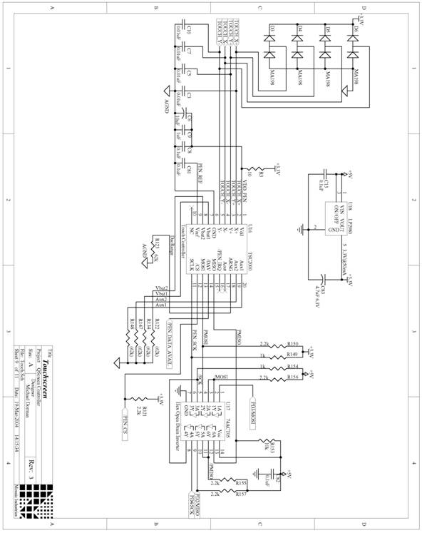
The following are detailed schematics for the QScreen Controller. The QScreen Controller integrates an embedded computer utilizing the 68HC11 microcontroller, along with a touch panel and an LCD (liquid crystal display) graphic user interface (GUI) that is well-suited for...
After answering all relevant questions and obtaining the necessary decisions, a thorough study of the PIC datasheet is essential to understand the steps for each configuration and other details. It is important to note that it is bit 3...
A stepper motor is an effective solution for achieving high-precision motion control. To operate a stepper motor, a corresponding control circuit is required. A stepper motor control circuit typically consists of several key components that facilitate the precise movement of...
For this week's assignment, a chip design was provided, and the task was to incorporate a button and an LED (light-emitting diode). The objective was to fabricate the chip and program it to interact with the light and button....