
C64 VICE Front-End
This project integrates a PIC microcontroller to facilitate modern interfacing with the classic Commodore 64 keyboard and joystick ports. The use of a USB interface not only modernizes the connectivity but also enhances the performance of the emulation experience. The design emphasizes ease of installation and reversibility, ensuring that the integrity of the original hardware is maintained. The matrix keyboard configuration is critical for accurate key detection, particularly in preventing ghost key issues, which can occur when multiple keys are pressed simultaneously. The meticulous reverse-engineering process underscores the importance of verifying hardware schematics against actual component behavior, especially in legacy systems where documentation may be flawed.
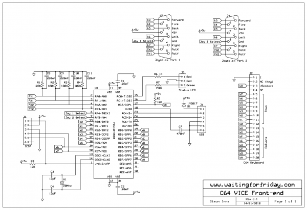
The integration of internal pull-up resistors simplifies the circuit design, reducing the number of external components required. The joystick interface is designed to be compatible with existing joystick hardware, allowing for a seamless transition from original to modern control schemes. The choice of the PIC18F4550 microcontroller provides ample processing power and USB support, making it a suitable choice for this application. Overall, this project stands as a testament to the ability to bridge the gap between vintage technology and contemporary standards, allowing enthusiasts to enjoy classic software with modern convenience.The aim of this project was to create a front-end for Commodore 64 emulation using VICE. One of the primary problems with emulators (especially for machines from the `80s) is that there was no standard keyboard arrangement. In this project I took a broken Commodore 64 computer and replaced the motherboard with a PIC microcontroller based board whi
ch interfaces the keyboard and both joystick ports (including ADC for the paddles) to a modern full-speed USB 2. 0 interface. The board is designed to fit inside the original Commodore 64`s `breadbox` case without requiring any modification to the original machine.
In fact it is possible to fit this interface and at a later point remove it and replace it with the original motherboard (we have to preserve what we have!) The Commodore 64 keyboard is a straight-forward matrix keyboard with 8 columns and 8 rows giving a total of 64 keys. There is also an additional RESTORE key which (in the original machine) was wired to the CPU to act as a non-maskable interrupt key (or `break` key).
In order to wire the keyboard up to the PIC controller I made a simple breakout adaptor for the keyboard connector (a 20-pin SIP female connector) and wired it to my PIC USB reference board (this board is actually a pin-compatible clone of the PICDEM FS USB board which I made myself): The reference board is useful because it acts as a `known working` USB implementation (this is so you know that only your software is wrong when it doesn`t work - otherwise debugging USB code can be a little tricky). Once connected I was able to test the keyboard and the method for connecting it to the PIC. I also decided to test the configuration of the keyboard matrix since this is very important for detecting `ghost keys` as you will see later in this article.
However, I was surprised to find out that the keyboard did not seem to match the schematic at all, when testing the matrix I saw ghost keys in the wrong places. Clearly, the C64 service manual was incorrect. In order to confirm this suspicion I took the keyboard apart so I could manually reverse-engineer the matrix wiring.
Firstly I took a picture of the PCB and then used photoshop to enhance the tracks on the board (a technique I used in my `reverse engineering the MB electronics Simon game` project). This gave me the following image: The next step is to trace the tracks on the PCB one by one (not a fun task!).
For the record the following two diagrams (hand-drawn complete with crossing-out) show the physical wiring of the keyboard: From the above diagrams you can clearly see that the letters marked on the PCB represent the columns in the keyboard matrix and the numbers represent the rows. Once I had the wiring mapped it was a simple case of tracing the wires from the keyboard back to the keyboard connector.
This proved the initial analysis correct; the C64 service manual is incorrect. The following diagram shows my corrected keyboard matrix and keyboard connector pin out, by using this version I was able to confirm that the matrix wiring assumed by the test code on the PICDEM FS USB board was correct (I also added in the `key number` to the matrix to help keymap coding and such like: From this diagram it was easy to create a good circuit for the PIC. I used the 8-bit portD to act as the `sink` for the columns and portB (with its internal pull-up resistors) for the rows.
Making use of the internal weak-pull ups of portB saves having a bunch of external pull-ups. For the two joystick ports I used a similar design to my previous Atari Joystick USB Adaptor project. I simply took the circuit design and remapped it over the keyboard matrix connections (and also changed it from a PIC18F2550 to a PIC18F4550).
The joystick detection works by selecting the joystick to scan by setting either RA4 or RA5 to sink the current from the desired joystick and then scanning portB to see if any switches are pressed. This tec 🔗 External reference
Related Circuits

Although a matching charger is typically included in the package, some devices can only be charged via a USB port. This is not surprising for USB MP3 players, which need to dock with a PC for file transfers. However,...

A schematic diagram is a layout of symbols and connections of every electronic component in a circuit, serving as a guide on how the circuit functions. Learning to read it may initially seem challenging; however, expertise in cellphone repair...
This document presents a compact Theremin module designed to connect to an Arduino board, which outputs sound to a speaker or generates control signals such as MIDI or servo commands. The device serves not only as a musical instrument...
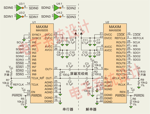
Low Voltage Differential Signaling (LVDS) is an effective digital video signal transmission interface that supports low-cost digital audio data streaming. This article discusses the use of Maxim Integrated Products Inc.'s MAX9205/MAX9206 10-bit LVDS serializer/deserializer (SerDes) to transmit up to...
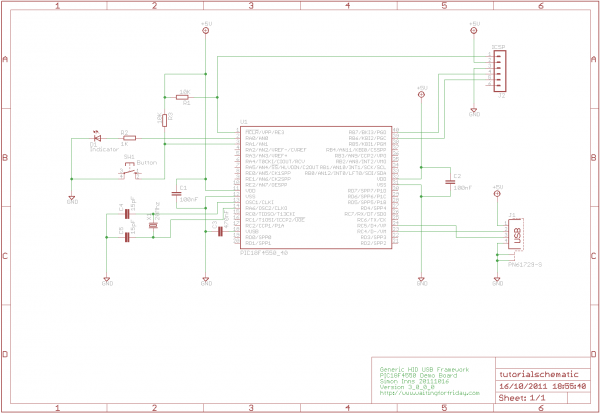
Utilize the Microchip C18 compiler based on the latest USB framework libraries for both the PIC and Windows. This will facilitate a smoother transition from basic tutorials to more complex projects. Feedback and suggestions are welcome on the forums....

This circuit provides a regulated output voltage ranging from 5 V to 15 V DC, which can be adjusted using a preset resistor. The current output can reach up to approximately 350 mA. An integrated circuit is utilized to...