
theremin as a capacitive sensing device

The Theremin module's design integrates several key components that ensure its functionality and reliability. The LC oscillator is the heart of the system, with L1 and C1 determining the resonant frequency. The choice of components is critical; L1 should have a high quality factor (Q) to minimize losses and ensure stable oscillation. The feedback mechanism provided by C3 is essential for maintaining oscillation, while the Gates ICs amplify the signal to a usable level. The digital conditioning performed by Gates D and C is crucial for interfacing with the Arduino, allowing for digital signal processing.
The enclosure of the circuit is important not only for physical protection but also for minimizing the effects of environmental factors on the oscillator's frequency stability. The choice of antenna length and material also plays a significant role in the performance of the Theremin, as it directly influences the sensitivity and range of the device.
The measurement process utilizing the Arduino's hardware counters is an efficient method for capturing the rapid frequency changes characteristic of the Theremin effect. The implementation of an interrupt-driven approach allows for precise timing and measurement, ensuring that even minor frequency deviations are detected and processed. The calibration routine further enhances the accuracy of the device, allowing it to adapt to changing environmental conditions and maintain consistent performance.
Overall, the Theremin module exemplifies a sophisticated integration of analog and digital electronics, leveraging the capabilities of the Arduino platform to create a versatile musical and sensing instrument.Here we show a little Theremin module which plugs onto a Arduino Board that gives out the tune to a speaker or puts out the tune as control signal like MIDI, Servo etc. We were using this device not only as a musical instrument, various kinds of proximity sensors, pointing devices or as interface in combination with Processing, Max or Pd have been
build with this technique. The Theremin Module itself is as little LC type Radio frequency oscillator which generates a radio wave and gives out the frequency signal to the Arduino board. The Arduino itself acts in this case as a accurate frequency meter which transforms this frequency deviation into sound or control signals.
Since you will find numerous articles in the Web describing the principle of a Theremin we leave here only that brief description. If you have a look at the Oscillator schematic you see the components L1 and C1 that are forming a resonator responsible for the oscillator frequency of about 4.
1 Mhz. The Gates IC1A and IC1B are building an analog amplifier block which is rising the oscillator signal to be fed back to the resonator. Capacitor C3 put an amount of energy back to the input as positive feedback so that an steady oscillation occurs.
The Gates D and C are conditioning the wave into a digital logic level squarewave signal for the Arduino board Care must be taken in the choice of the parts L1 and C1. C1 must be a ceramic capacitor NP0 type (zero temperature coefficient) and L1 a high Q inductor suitable for high frequency such as a Neosid 00612299 but for the first test a standard 10uH Choke will do also the job.
Because the oscillator frequency tends to drift by ambient temperature changes the circuit should be capsuled in a little plastic box. The antenna length should be not longer than about one meter, good results can be obtained with a ring of 1, 5mm steel wire which provides also a good mechanical stability to avoid swinging or vibration.
Most of the drift or other unwanted side effects are compensated by the software. It must be noticed that also that all metal parts like usb cable, connected speaker, even the connected computer are loaded by the RF signal and tend to be hot so that they work as antenna as well. To measure the oscillator frequency the output is connected to digitalinput 5 of the Arduino Board. This pin has an alternate function as an input of the ATMEGA internal hardware Counter1 unit. If configured by software, every time a level change is present on that pin the counter is advanced by one.
That happens in our case about 4 million times a second. The hardware Timer2 unit is used as a timebase to start and stop counting in a interval of exactly 1/10 second. After that period the counter value reads about 410. 000 so we yield a measurement resolution of 10Hz which is what we need to see the slight frequency deviation caused by the Theremin effect.
Since the Counter1 unit is only a 16 Bit counter several overflows occur during the measurement. These overflows are counted in the timebase section to be assembled after the measurement period to a long int result. The whole timing is done in an interrupt function which is invoked by the timer2 all 2 milliseconds. If the end of a timebase period is reached a flag as a global variable is set to signal the main function the presence of a new value.
Since only the frequency differences not the absolute value are of interest for us, the consecutive values are substracted from the first frequency value after startup. An autocalibration to eliminate long term frequency drift is performed after a number of measurement cylces when the deviation is smaller then a certain threshold value.
The threshold value and the number of cycles to calibrate has to be customized to the application. /* Theremin Test * * Therremin with TTL Oscillator 4MHz * Timer1 for freauency measurement * Timer2 for gate time * connect Oscillator on digital pin 🔗 External reference
Related Circuits
Capacitive sensors are utilized in various devices, ranging from consumer electronics to industrial and process control systems. Touch buttons are increasingly integrated into lamps and dimmers, while motion detectors can sense minute changes in deflection. Hygrometers measure humidity levels,...
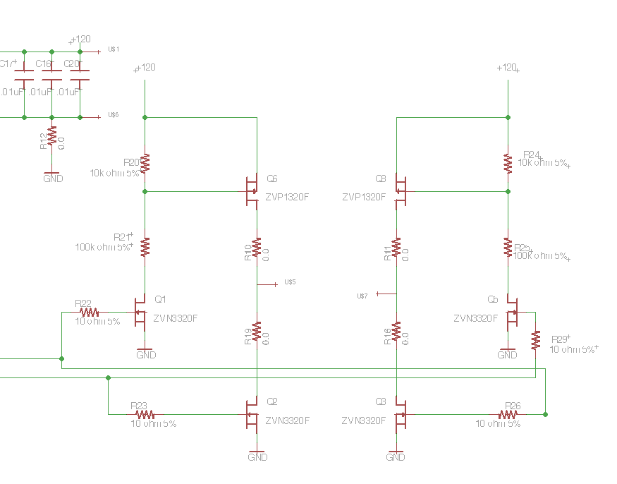
Following the publication of a previous post, some unusual issues were encountered, which required several days to clarify. The main focus was on building a simple Class D amplifier designed to provide an EL panel with a +/- 120V...
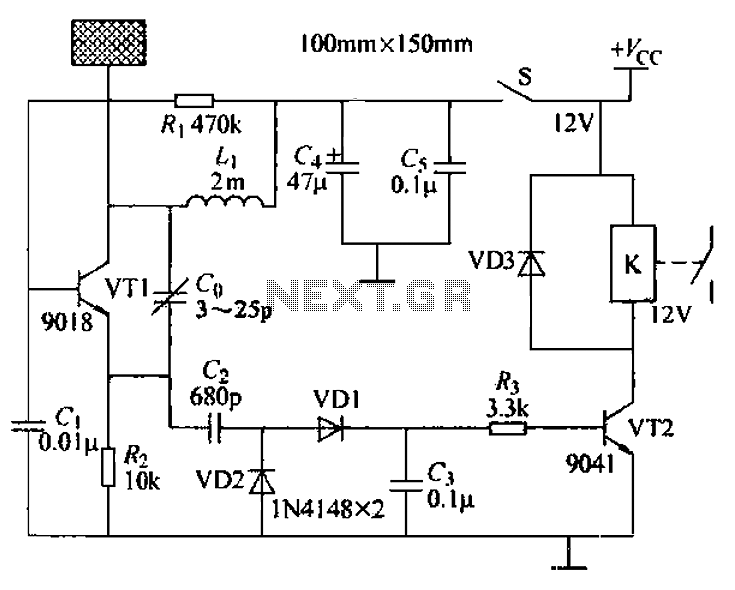
A capacitive proximity controller typically consists of a radio frequency oscillation circuit and a detection plate. The circuit is constructed using discrete components for capacitive proximity sensing detection. The transistor VT1, along with surrounding components, forms a radio frequency...
Here is the schematic of the device depicted in the photo. Each of the ten coil-assemblies has its own copy of the above circuit. The SS41 is a Microswitch Hall Effect magnetic field sensor IC that was found in...
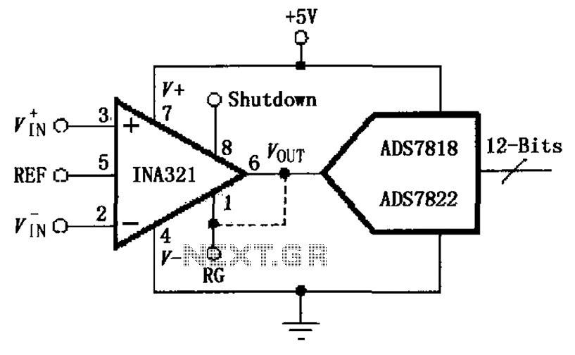
The INA321/322 is configured to directly drive the capacitive input of an A/D converter. Due to its low output resistance, the INA321/322 can effectively handle high frequency signals and directly drive capacitive loads. The input voltage is amplified by...
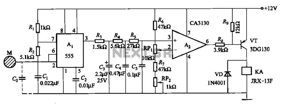
The circuit utilizes a 555 IC in conjunction with capacitors C1, C2, and a metal plate (tablet) M to create a distributed capacitance Co and resistor R1 connected to ground. Resistor R2 forms a self-excited multivibrator, while resistors R3...