
Building a PIC18F USB device

The circuit design begins with the PIC18F4550 microcontroller, which serves as the core of the USB device. This microcontroller features integrated USB capabilities, allowing for seamless communication with host devices. The USB type B connector is essential for establishing the connection to the PC, while the ICSP header provides an interface for programming and debugging the microcontroller during development.
The inclusion of a single LED and a push-button switch creates a simple user interface. The LED serves as an output device, indicating the status of the device or responding to commands from the PC. The push-button switch acts as an input device, allowing user interaction that can be detected by the firmware running on the PIC microcontroller.
Powering the device through the USB connection eliminates the need for additional power supply components, simplifying the circuit design. The use of the 470nF capacitor is critical for ensuring stable operation of the USB interface. This capacitor helps filter noise and stabilize the voltage levels necessary for reliable USB communication.
The firmware developed for the PIC18F microcontroller will handle USB communication, interpreting commands from the PC to control the LED and read the state of the push-button. The software developed in Microsoft Visual C# will provide a user-friendly interface on the PC, enabling users to interact with the USB device easily.
Overall, this project serves as an educational platform for understanding USB device development, focusing on the principles of two-way communication, firmware development, and user interface design. The simplicity of the design and the use of readily available tools and components make it accessible for individuals looking to expand their knowledge in USB device creation.Use the Microchip C18 compiler to be based around my latest USB framework libraries for both the PIC and Windows. This should provide a smoother path from this basic tutorial to more complex projects. As always I welcome your feedback and suggestions over in my forums. I get a number of emails everymonth asking about creating USB devices using the PIC18F microcontroller.
After looking at projects such as my Atari Joystick USB Adaptor and C64 VICE Front-End there seems to be a demand for more information on how to `hack your own`. In this article I will show how to breadboard a simple USB generic HID device, creating the PIC18F firmware and finally creating the Windows interface for the device which will allow you to control a LED from the PC and read the state of a push-button from the device.
Since the advent of Windows 7 you need an expensive Microsoft validation certification to create custom USB drivers (without it most users cannot even install your software). Using the built in drivers for generic HID devices provides a simple method of creating Windows and Linux compatible devices and also makes the creation of both firmware and software far simpler.
Since the HID standard does not require custom drivers you will not need to get a certificate for your driver, also both Windows and Linux have built-in libraries to help you communicate. For this article we`re going to stick to a fairly basic USB device. The device will allow you to control a LED from Windows and also see the status of a push-switch on the device.
Using this the basic principals of 2-way USB communication will be made clear allowing you to progress onto more complex projects. To keep the cost and difficulty as low as possible I will concentrate on breadboard construction of the hardware using few components, the PIC18F firmware will be based on (the freely available) MPLAB and Microchip C18 compiler, the Windows software will be created using Microsoft Visual C# 2010 express (which is also free to download).
Although this article is based around the PIC18F4550 microcontroller you can easily substitute this for the smaller and cheaper PIC18F2550 which is code compatible with the larger 4550. If you want to follow along with this article I suggest you scroll down to the bottom and download the accompanying software.
Also make sure you have MPLAB, Microchip C18 for the PIC18F and Microsoft Visual Studio 2010 express installed. Please note that all of the host screenshots are taken from a Windows 7 machine, if you need to find the same/similar thing on an older Windows box please head over to Google where you will find plenty of information about where the items are on your WindowsME machine.
To begin with we need to build a USB device to communicate with. In the following circuit diagram you can see the minimum configuration for a usable USB device. The device includes an ICSP header (In Circuit Serial Programming) and a USB type B connection. In addition there is a single LED and a single push switch to represent the input and output devices. The circuit is very straight forward (if you are not familiar with this level of microcontroller electronics I suggest you go ahead and build some of the many flashing LED and push button tutorials available on the web before attempting this).
The PIC18F4550 will be `bus powered`; this means that the device will draw its power from the USB host (your PC) so no power regulation is required. The 470nF capacitor (C3) is required so the PIC can operate the internal USB circuitry (it helps with regulating the USB voltages required by the on-board USB interface in the PIC) - Note that C3 can be any value between 220nF and 470nF (the datasheet recommends 220nF however I had 470nF available, it doesn`t make any odds to the functioning of the circuit.
The ICSP header allows you to connect a PIC programmer, I suggest u 🔗 External reference
Related Circuits
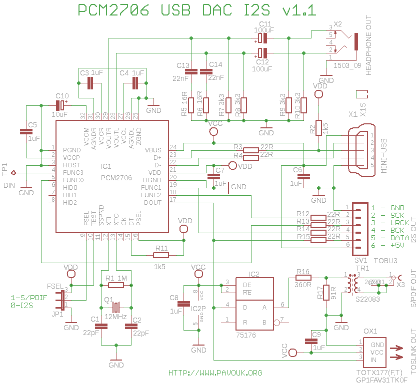
This project involves a couple of USB Digital-to-Analog Converters (DACs) that lack I2S output. Some users do not require S/PDIF input and prefer a direct USB connection. Therefore, it is unnecessary to convert the signal from USB to S/PDIF...
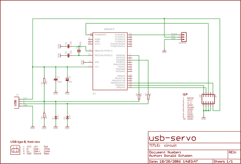
The USB-Servo is a device designed to control a servo motor via a USB connection. Servos are motorized components commonly utilized in remote-controlled cars and airplanes. This specific device was created to activate a toy puppet. The puppet is...
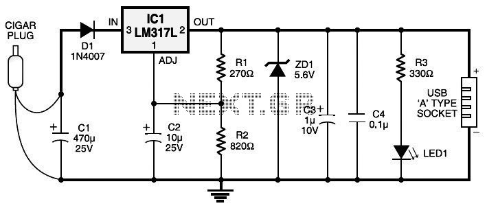
Currently, nearly all computer systems include logic blocks designed for interfacing with a USB port. In practical terms, a USB port can provide more than 100 mA of continuous electric current at 5V to the peripherals connected to the...
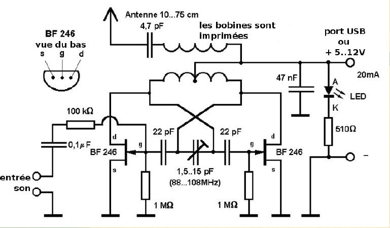
Here is a small FM transmitter circuit designed for desktop or laptop use, allowing users to enjoy movies and music from a distance. This USB-powered FM transmitter connects to a computer or MP3 player and broadcasts on a tape...
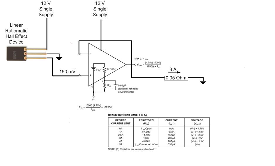
The proposed approach would dissipate (12V)(3A) = 36 watts, which results in significant heat generation in the circuit. This necessitates consideration of two alternatives: 1) Operating the op-amp at a lower supply voltage, if feasible, or 2) Utilizing a...
The Universal Serial Bus (USB) has become a widely adopted technology for connecting computer peripherals. It is present on nearly every new computer and typically offers a seamless connection method for a variety of consumer electronics devices such as...