
caller id project
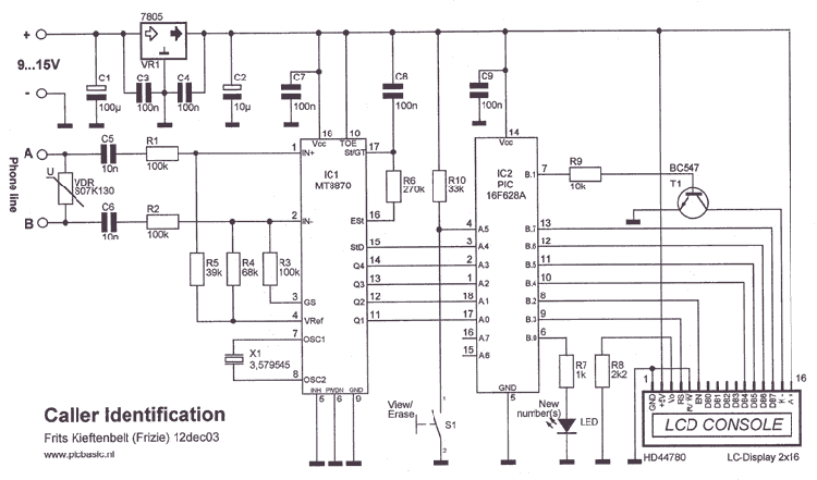
The project involves utilizing the PIC 16F628A microcontroller to decode caller ID signals, which are transmitted during the ringing phase of a telephone call. The MT8870 is a dual-tone multi-frequency (DTMF) decoder that converts the received audio tones into binary-coded decimal (BCD) output, which can then be processed by the microcontroller.
To ensure proper operation of the MT8870, several factors must be considered. First, verify the power supply connections to the MT8870, ensuring that the VDD and GND pins are correctly connected to the appropriate voltage levels, typically +5V. It is essential to check the crystal oscillator connected to the MT8870, as the correct frequency (usually 3.579 MHz) is crucial for accurate tone detection.
Next, inspect the audio input to the MT8870. The input should be connected to the telephone line in a manner that captures the caller ID signal effectively. A suitable coupling circuit may be required to interface the telephone line with the decoder, often involving capacitors and resistors to filter and condition the signal.
Additionally, the connection between the MT8870 and the PIC 16F628A must be verified. The BCD output pins from the MT8870 should be connected to the appropriate input pins on the microcontroller. Ensure that the pull-up resistors are used where necessary to maintain stable logic levels.
Lastly, debugging can be facilitated by using an oscilloscope to observe the output from the MT8870 and confirm that it is producing the expected BCD signals when a caller ID signal is present. This will help identify whether the issue lies with the decoder or the subsequent processing by the microcontroller.Doing the caller id with the pic 16f628A. My programming and ic are working very well but my mt8870 decoder is not working. i need some help here. i stay in Malaysia please help if anyone got any idea 🔗 External reference
Related Circuits
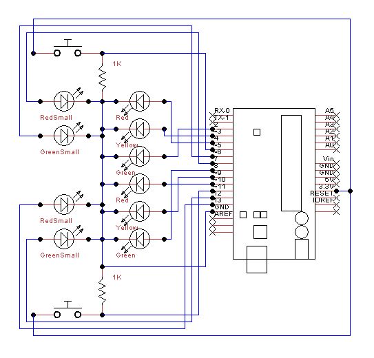
Set up the lights on the breadboard to resemble a traffic light configuration. The red LED should be positioned at the top, followed by the yellow LED, and then the green LED. The small red and green LEDs will...
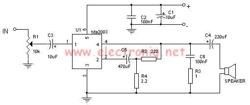
The TDA2003 audio amplifier integrated circuit can be used to design a straightforward 10-watt power audio amplifier for a 2-ohm load or 4 watts for a 4-ohm load. The TDA2003 offers high output current capacity (up to 3.5A) and...
The project described is a digital implementation of the book cricket game, which is commonly played by Indian students during their childhood. The core component of the project is an 8-bit microcontroller from the AVR family known as the...
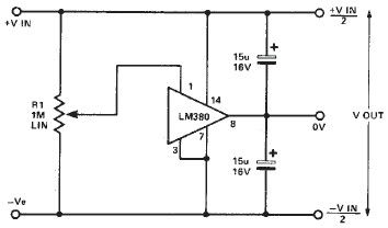
A simple split power supply circuit can be designed using the schematic diagram based on the LM380 audio power integrated circuit (IC). The output voltage regulation is dependent on the circuit feeding the LM380. The power dissipation is approximately...
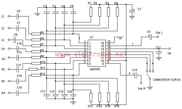
The TDA1029 is a dual operational amplifier configured as an impedance converter. Each amplifier features four mutually switchable inputs that are safeguarded by clamping diodes. Signal sources can be switched in various modes. The electronic components required for this...
This circuit consists of four 1N4148 diodes connected in series with a thermal anticipation resistor (R1) heat-shrunk together at the end of a three-wire signal cable, which is visible in some photos. The thermal anticipation resistor is an old...