
Power pulse circuit by LM350 and NE555
The power pulse circuit utilizes the LM350 voltage regulator in conjunction with the NE555 timer IC, forming a versatile system capable of driving various loads such as lamps, LEDs, and DC motors. The LM350 serves as an adjustable voltage regulator, allowing for precise control over the output voltage and current, which is essential for applications where specific power levels are required.
The NE555 timer is configured in astable mode, generating a continuous square wave output. This square wave can be used to modulate the input to the LM350, effectively controlling the power delivered to the load. The frequency of the pulse can be adjusted by changing the resistor and capacitor values connected to the NE555, providing flexibility in operation.
R5 is a crucial resistor that controls the amplitude of the output pulse. By adjusting R5, the user can modify the peak voltage supplied to the load, ensuring that it operates within safe limits. This is particularly important when driving sensitive components like LEDs, which can be damaged by excessive voltage.
R1, on the other hand, adjusts the output power by influencing the voltage regulator's feedback loop. This adjustment allows for fine-tuning of the power supplied to the load, accommodating different load requirements and ensuring efficient operation.
The circuit design should include appropriate filtering capacitors at the output of the LM350 to stabilize the voltage and minimize ripple, especially when driving inductive loads such as motors, which can introduce noise and voltage spikes into the circuit. Additionally, proper heat sinking for the LM350 is recommended, as it may dissipate significant heat during operation, especially under high load conditions.
Overall, this power pulse circuit is a robust solution for various applications requiring controlled power delivery, with adjustable parameters to cater to different operational needs.Power pulse circuit by LM350 and NE555 . This circuit can use to drive lamp,power LED,DC motor etc. Adjust R5 for output amplitude.Adjust R1 for output power .The LM350 is adjustable 3-terminal. 🔗 External reference
Related Circuits
Battery Indicator Circuit for the Caravan. This i-TRIXX circuit can prevent a lot of trouble for those who go on holiday in a caravan. It would be a significant damper on your holiday spirit when you are unprepared. The Battery...
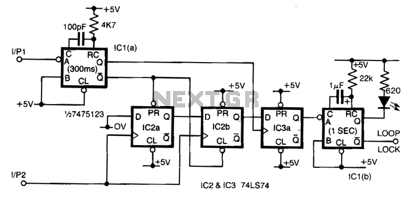
Input 1 functions as a gating period, during which a single rising edge on input 2 produces a logic 1 output. Any other input that indicates non-identical frequencies results in a logic 0 output. IC1a converts input 1 into...
This circuit functions with inaudible (ultrasonic) sound. Sound of frequency up to 20 kHz is audible to human beings. The sound of frequency above 20 kHz is called ultrasonic sound. The circuit described generates (transmits) ultrasonic sound of frequency...
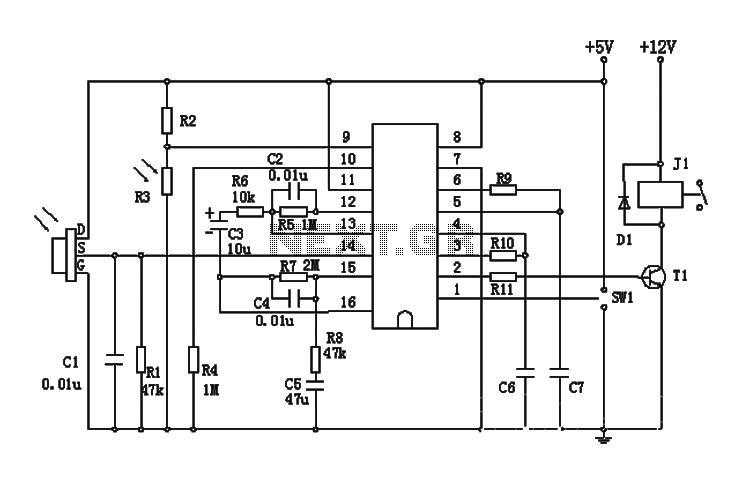
The BISS0001 is a high-performance integrated circuit designed for sensor signal processing. When combined with pyroelectric infrared sensors and a minimal number of external components, it forms a passive pyroelectric infrared switch. This device can automatically and quickly activate...
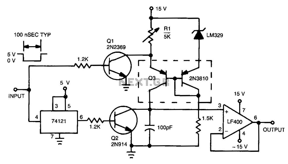
This circuit functions by charging a small capacitor using a constant-current source when a measurable pulse is present. The dual PNP transistor Q3 acts as the current source, with its output current determined by dividing the LM329 reference voltage...
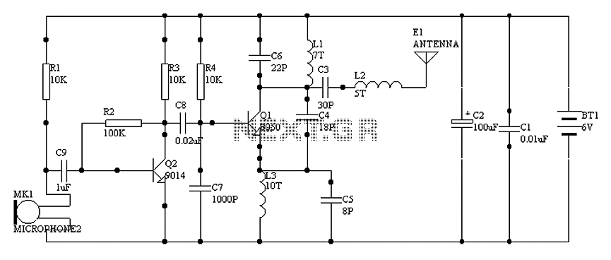
1000 m single-tube FM transmitter circuit diagram of oscillation. The circuit diagram for a 1000 m single-tube FM transmitter is designed to generate frequency modulation signals suitable for transmission over a distance of approximately 1000 meters. This transmitter employs...