
Capacitance Meter Using 555 Oscillator

The 555 timer IC is widely used in various applications, including oscillators, timers, and pulse generation. In the astable mode, the frequency (f) of the output waveform can be calculated using the formula:
\[
f = \frac{1.44}{(R_1 + 2R_2)C}
\]
Where:
- \( R_1 \) is the resistance connected between the supply voltage and the discharge pin (pin 7).
- \( R_2 \) is the resistance connected between the discharge pin (pin 7) and the threshold pin (pin 6).
- \( C \) is the capacitance connected between the threshold pin (pin 6) and ground.
The duty cycle can also be calculated to determine the proportion of time the output is high versus low, which is given by:
\[
D = \frac{R_2}{R_1 + 2R_2}
\]
This formula indicates how the values of \( R_1 \), \( R_2 \), and \( C \) influence the frequency and duty cycle of the output signal. The 555 oscillator can be configured to produce a square wave output, which is useful in generating clock pulses for digital circuits, frequency modulation, and tone generation.
In practical applications, it is essential to select resistor and capacitor values that are within the operational limits of the 555 timer to ensure stable and reliable performance. The frequency can be adjusted by varying the resistor values or the capacitance, allowing for versatile applications in timing and waveform generation circuits.The frequency formula of 555 oscillator is popularly known. For a known resistors and capacitor, the frequency can be determined by a formula. From the math. 🔗 External reference
Related Circuits
This circuit is an Audio Decibel Level Meter that utilizes the SA604 integrated circuit, which is designed as an RF device and also serves as a Received Signal Strength Indicator (RSSI). In cellular radio applications, the radio's microcomputer continuously...
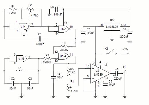
The NAND gates utilize a CMOS 4011 chip, which is a low-power component ideal for battery-operated circuits. This chip is powered by a 5V voltage supplied from an LM7805L regulator. The purpose of this regulation is to maintain a...
More: The provided input lacks specific details or context regarding an electronic circuit or schematic. To create a comprehensive electronic schematic description, it is essential to include key components, their interconnections, and the overall functionality of the...
This multimeter is designed to measure output voltage and current in a power supply unit (PSU), with the current sense shunt resistor connected in series with the load at the negative voltage rail. It operates using a single supply...
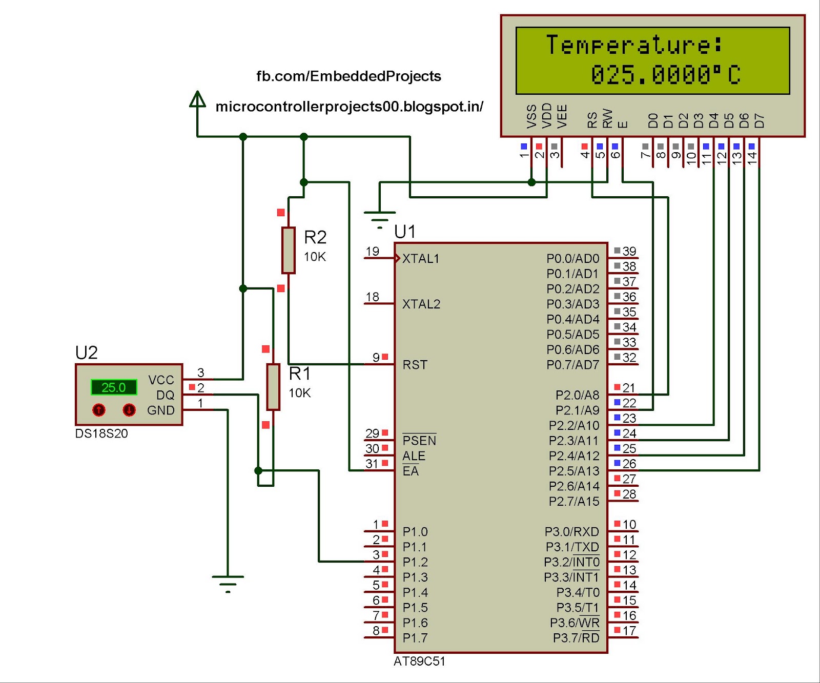
The hardware configuration for utilizing multiple 1-Wire temperature sensors, such as the DS1820, is straightforward. Communication between the microcontroller and the temperature sensors occurs over a single-wire bus, which can also supply power to the devices. An extensive number...
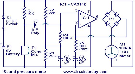
This circuit is a simple sound level checker, useful for setting up home theater systems by testing sound pressure levels across different channels and positions in a room. The design features a non-inverting amplifier utilizing the CA 3140 operational...