
Sound pressure meter

The sound level checker circuit is designed to facilitate accurate sound pressure measurements essential for optimizing audio setups. The core component, the CA 3140 operational amplifier, operates in a non-inverting configuration, providing high input impedance and low output impedance, which is ideal for interfacing with the condenser microphone.
The condenser microphone generates an analog voltage signal proportional to the sound pressure it receives. This signal is fed into the non-inverting input of IC1. The gain of the amplifier can be set using external resistors, allowing for flexibility in sensitivity based on the expected sound levels in the environment.
After amplification, the signal is routed to the bridge rectifier (D1), which converts the AC signal produced by the microphone into a DC voltage suitable for driving the meter (M1). The rectification process ensures that the meter provides a readable deflection corresponding to the average sound pressure level, allowing users to assess the audio output effectively.
The inclusion of switch S1 provides a simple means to control the power to the circuit, ensuring that it can be easily turned on or off as required. This feature enhances usability, especially in temporary setups where the circuit may need to be used intermittently.
Overall, this sound level checker circuit is a practical tool for audio enthusiasts and professionals alike, enabling precise adjustments to sound systems to achieve optimal performance in various listening environments.Here is a simple circuit that can be used to check the sound levels. The sound pressure meter is vey useful in setting up home theater systems, if you need to test the sound pressure of each channels on different positions in the room. The circuit is nothing but a non- inverting amplifier based on op-amp CA 3140 9 (IC1). The sound picked by the con denser mic will be amplified by the IC1 and rectified by the bridge D1 to drive the meter M1. The deflection on the meter will be proportional to the pressure of the sound falling on the mic. The switch S1 can be used as an ON/OFF switch. 🔗 External reference
Related Circuits
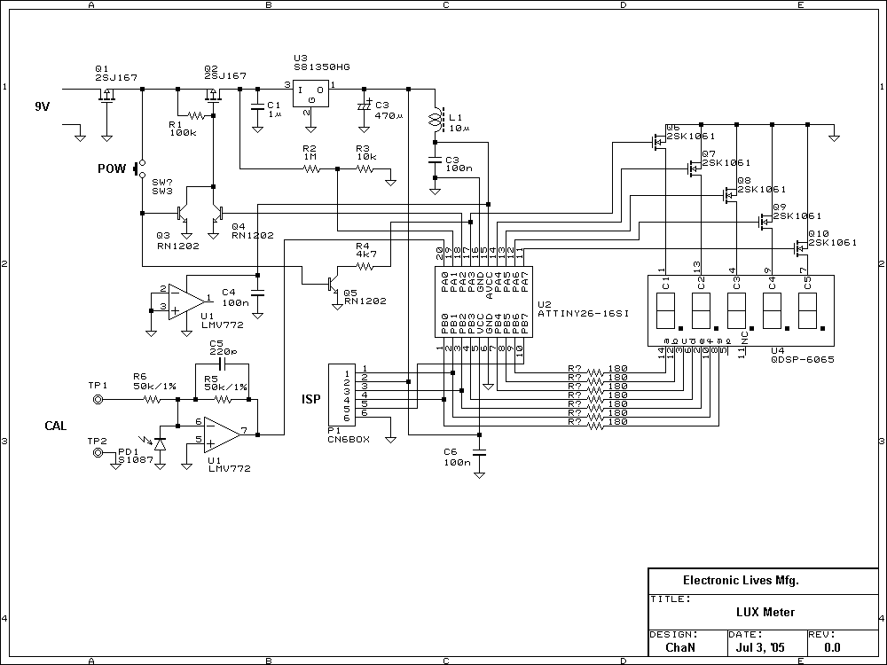
Photo diode outputs light current that is well proportional to input light power when it is used in short mode. In this lux meter, the output current is converted to voltage with an I-V converter, it is captured by...
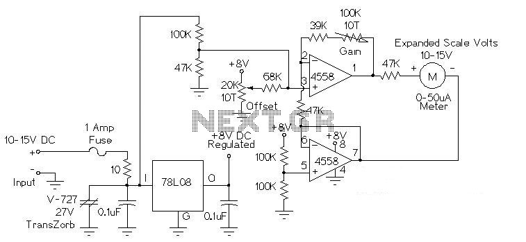
This circuit is used to measure the voltage on a 12V (nominal) lead acid rechargeable battery system. It was specifically designed for use in solar powered systems, but is general enough that it can be used for automotive or...
This sound effects circuit is designed to function as a signal distorter. When utilized with an electric guitar, it enables the creation of unique sound effects. The sound effects circuit operates by manipulating the input audio signal from the electric...
In this project, you will make a simple low-power broadcast-type circuit, using a crystal oscillator integrated circuit and a collector modulated AM oscillator. You can connect the circuit to an electret microphone (pointed out in gray on the diagram)...
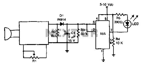
The acoustic detector consists of a Schmitt trigger IC555 connected to various components. When the input exceeds a certain voltage, the output will change state from high to low. R4 is used to set the threshold voltage. The acoustic detector...
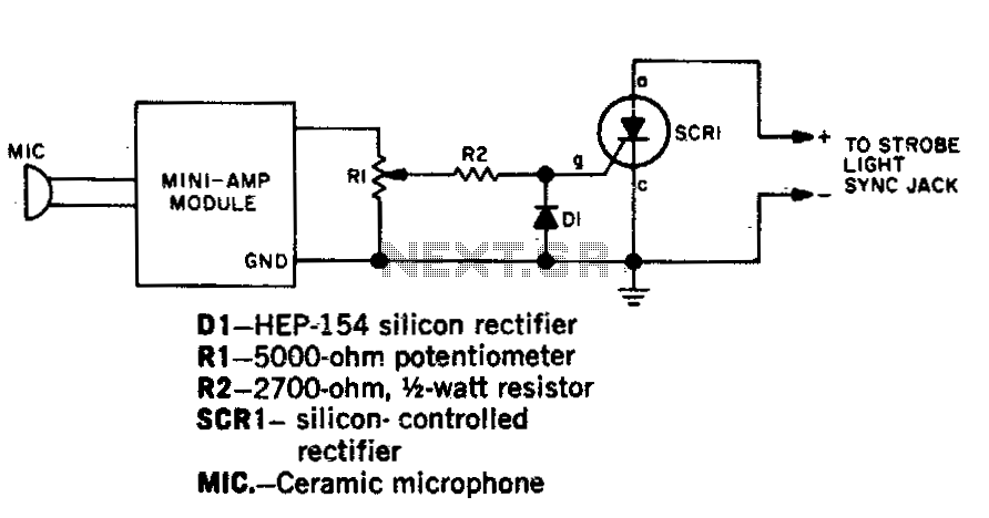
Capture strobe-flash images at the precise moment a pin punctures a balloon, a hammer shatters a lamp bulb, or a bullet exits a firearm. Utilize a transistor amplifier rated at 1 watt or less, which must include an output...