
Voltmeter + Ammeter LCD panel
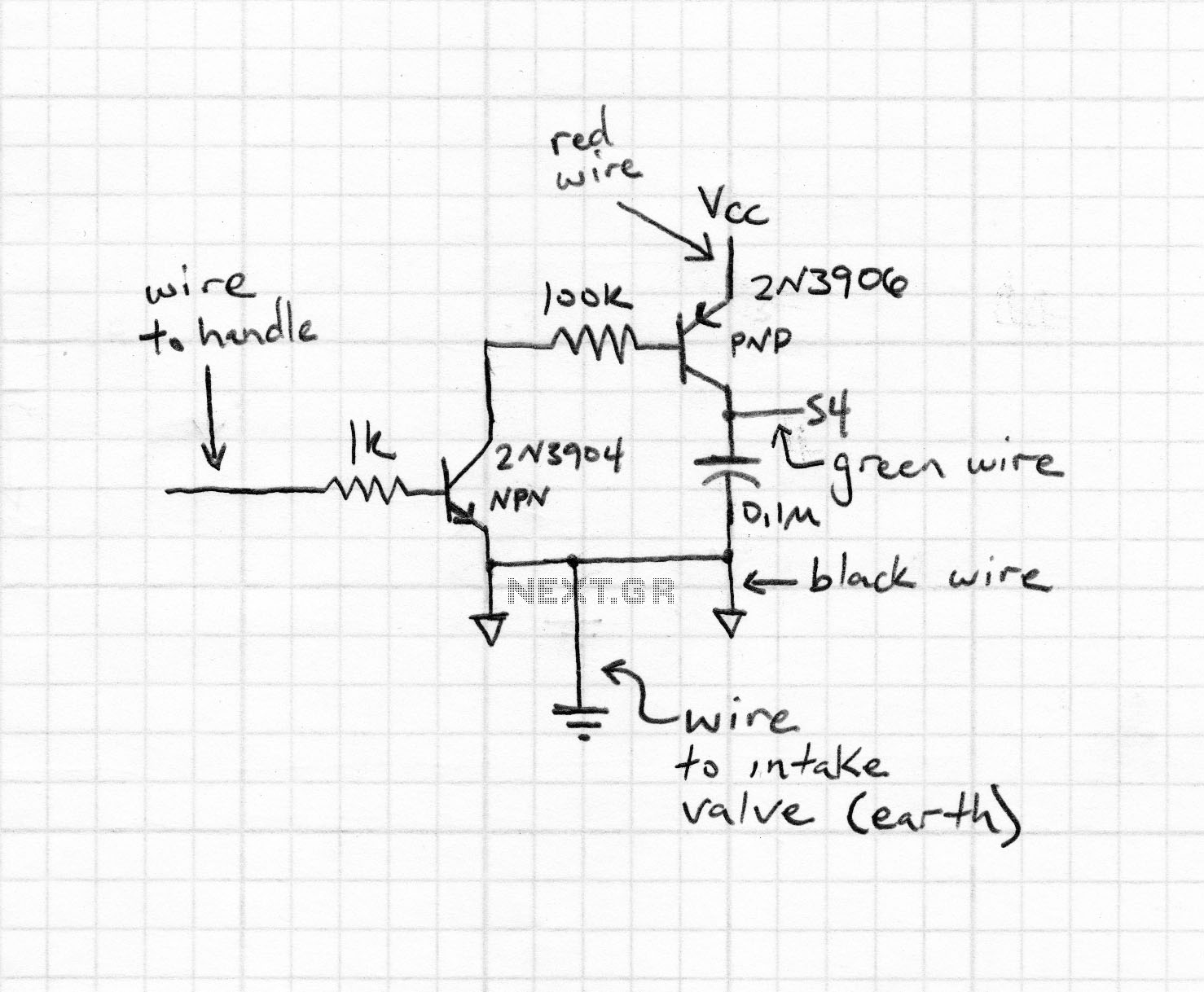
sed to cool the main heatsink. The power threshold at which the fan switches on can be adjusted using One Touch Button Setup. Bellow you can see the multimeter schematic. There are some components in the parts list marked as "Do Not Assemble". That components was needed in a previous software edition. Current software version doesn`t need them, so you just don`t add them. Maybe in a future version of the multimeter there will be a simpler PCB with simpler electronic diagram too. PCB files are> here <. There are two version of PCB - normal and mirrored. I think, that anyone who makes PCBs will know which one should be used to produce right PCB. Optional element - protect Q1 against voltage peek after switch off fan. Most of the computer type fans which I tested didn`t produce voltage peeks dangerous for Q1 Optional element - protect Q1 against voltage peek after switch off fan.
Most of the computer type fans which I tested didn`t produce voltage peeks dangerous for Q1 Because µC is in TQFP package, we can program it after solderingall components on PCB. After that, programming is quite easy to perform. Programming signals are delivered through LCD connector. To make the programming cable, you can use an old PC HDD cable. Picture of my programming cable is shown here: Remembered, that during programming, the circuit must be supplied with +5V.
Depending on your programmer, supply voltage is provided either by programmer, or from separate power supply unit. After connecting µC to prog, you should check, if µC is "visible" for prog. When everything is fine, you can upload code to µC. The code is available> here <. It is assumed that µC is new and works with its internal RC clock at 1MHz. If not, set appropriate fuse bits to achieve above mentioned conditions. In addition Brown-out detector should be turned on by enabling BODEN fuse. Recommended Brown-out Reset Threshold Voltage is 4V. The next thing to do is to cross LCD soldering pads number 1 and 5. That`s necessary to provide groundfor LCD RW signal. After all, connect LCD module with the multimeter PCB. It is recommended to use a detachable connector for further expandability e. g. software upgrading. When pushing this button the shunt resistor value appears. If the resistor valueis known, repeat button pushing until correct value reached. If resistor value is unknown (e. g. self made resistor), short PSU output by ammeter, set some current by PSU current limit regulator and then, push button, lead to equal current indication on ammeter andmultimeter.
After resistor value setup, button must not be pressed for about 5 seconds. The next parameter to set up is fan switch-on power threshold. It is not the real powerloosed on output transistor (transistors), because multimeter has information on voltage drop on transistor and driving current. To avoid instability switch-off threshold is automatically set to 20% less than switch-on one. To reduce ADC conversion errors like un-linearity, gain factor etc. measuring range is divided into two sub-ranges 0-10V and 10-30V (switch thresholdcan be between7-13V depend on sourcing current and elements tolerance).
There is over-samplingapplied in multimeter software, so measuring resolution is the same in fine and coarse circuit and is 10mV. Because of the reason described above multimeter has two measuring circuits. To regulate coarse sub-rangeconnect voltmeter to PSU output, set up voltage at about 19V and turn R10 until voltmeter and multimeterindication are equal.
(If you posses 4. 5 digit voltmeter, you could regulate at voltage 30V) 🔗 External reference
Related Circuits
In many projects, alphanumeric LCDs driven by Hitachi's industry-standard HD44780 controller are utilized. These displays can operate in either 4-bit or 8-bit mode. In 4-bit mode, only the high nibble (D4 to D7) of the display's data bus is...
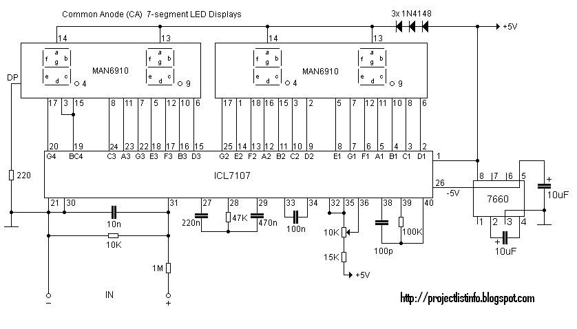
This digital voltmeter is suitable for measuring the output voltage of a DC power supply. It features a 3.5-digit LED display with a negative voltage indicator, capable of measuring DC voltages from 0 to 199.9V with a resolution of...
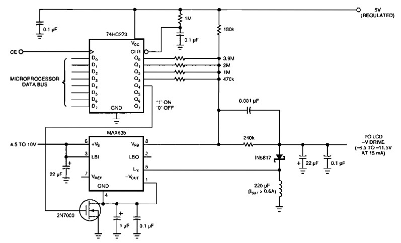
The following figure's switching regulator generates a negative voltage from the notebook battery supply. The microprocessor data bus drives a 4-bit DAC (74HC273), which can vary the regulator output between 6.5 to 11.5 V. This arrangement enables a staircase...

A high-input-resistance operational amplifier (op-amp), a bridge rectifier, a microammeter, and several discrete components are necessary to implement this versatile circuit. This circuit can measure DC, AC RMS, AC peak, or AC peak-to-peak voltage by simply altering the resistor...
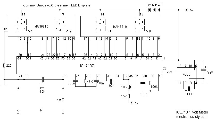
This digital voltmeter is ideal for measuring the output voltage of a DC power supply. It features a 3.5-digit LED display with a negative voltage indicator. The device measures DC voltages from 0 to 199.9V with a resolution of...
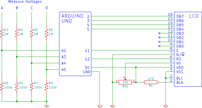
An Arduino voltmeter that displays voltage on an LCD display. The voltmeter has 4 channels for measuring four different voltages. The Arduino voltmeter utilizes an Arduino microcontroller to measure and display voltage levels on a Liquid Crystal Display (LCD). This...