
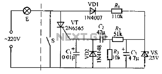
Capacitance switched light

The described circuit operates as a simple touch-activated light using a battery as the power source. The circuit's activation mechanism relies on the principle of capacitive sensing, where the human body acts as a conductor. When a finger touches the two metal strips, it completes the circuit, allowing a small amount of current to flow. This current is then amplified by the 2N3906 transistor, which is configured as a common-emitter amplifier. The amplified output is sufficient to trigger the SCR, a semiconductor device that can control the flow of current.
The SCR remains in a conducting state once triggered, allowing current to pass through the light bulb, thus illuminating it. The internal bimetal switch within the circuit is designed to cut off the current after a predefined duration, causing the light to turn off. This switch operates based on thermal expansion; as current flows through it, it heats up and eventually bends to open the circuit.
Once the bimetal switch opens, the current stops flowing, and the SCR is no longer held in a conducting state. This allows the SCR to return to its off state, ready to be triggered again by the next touch. The design ensures that the light operates only for a limited time, providing a practical and energy-efficient solution for temporary lighting needs.
For practical implementation, it is essential to select appropriate values for the resistors and capacitors in the circuit to ensure reliable operation and to prevent unwanted triggering. Additionally, the choice of the light bulb should align with the battery voltage to optimize brightness and battery life. The overall layout of the circuit should minimize resistance and interference to ensure consistent performance.The battery powered light turns on easily, stays on for just a few seconds, and then turns off again. The circuit is triggered when you place a finger across the gap between two strips of metal, about l/16th inch apart.
Enough current will flow through your finger to trigger the SCR after being amplified by the 2N3906. Once the SCR is fired, current will flow through the bulb until its internal bimetal switch turns it off Once that happens, the SCR will return to its nonconducting state. 🔗 External reference
Related Circuits

An efficient automatic solar garden lights circuit with minimal components. The advantage is that it operates entirely autonomously, with the solar panel functioning as a light detector. It switches the lamp off at dawn, charges the battery during the...

In this circuit, A = 1, port = 0.5, and it features a passive vent filter without distinction. Attention is required when the circuit is dry; Q is determined by the formula Q = 1 / (3 - A)....
A delay circuit using an improved quenching lamp pull switch is described, focusing on its performance and the delay function in lighting control. The circuit exhibits a high degree of stability and reliability. When switch S is closed, the...
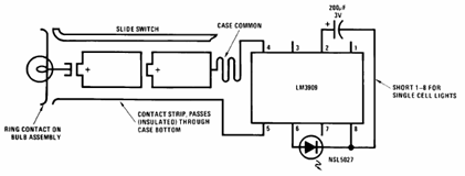
The schematic presented below illustrates the Flashlight Finder circuit diagram utilizing the LM3909, a monolithic oscillator specifically designed for flashing Light Emitting Diodes (LEDs). The Flashlight Finder circuit employs the LM3909 integrated circuit, which is capable of generating a series...
A dimmer for individual LED bulbs. LEDs (light emitting diodes) are very sensitive components; exceeding their rated current or voltage can drastically reduce their lifespan from over 50,000 hours to mere microseconds. LEDs are current-driven, meaning that the intensity...

A capacitance multiplier simulates a high-capacitance capacitor for analog signal processing. By utilizing a Digital-to-Analog Converter (DAC), it is possible to emulate... A capacitance multiplier is a circuit configuration that effectively increases the apparent capacitance seen at its output compared...