
LED Dimmer Lighting
A more effective method for dimming LEDs is through Pulse Width Modulation (PWM). With PWM, LED strings can be driven at their recommended forward current, with dimming achieved by rapidly switching the LEDs on and off at a frequency that is imperceptible to the human eye. The perceived brightness of the LEDs is determined by the ratio of the on time to the off time, known as the duty cycle. For instance, if the LED is on for 9 milliseconds and off for 1 millisecond, the duty cycle would be 90%, resulting in an intensity approximately equal to 90% of its maximum brightness. The simplest way to implement high-frequency switching is through a 555 timer integrated circuit (IC), one of the most widely used and versatile ICs available. The circuit described is intended for use as a dimmer for 12V DC light bulbs or as a speed controller for a 12V DC motor. In testing, the resistors in the LED strings were selected to provide a forward current of 25mA per LED. With three equal strings, the total current was 75mA, prompting the selection of a transistor (BC547) rated for 200mA to ensure reliability. This dimmer circuit operates within a duty cycle range of 5% to 95% as the potentiometer (P1) is adjusted from minimum to maximum. By substituting germanium diodes for the two IN4148 signal diodes, the dimming range can be extended to 1% to 99%. While simple components can create effective dimmers, utilizing a microcontroller often provides enhanced flexibility, speed, and ease of development. Numerous microcontrollers are available that are inexpensive, easy to program, and can be integrated into circuits with minimal external components, allowing rapid experimentation without necessitating physical alterations to the circuit board.
The LED dimmer circuit using PWM with a 555 timer can be designed as follows: The 555 timer is configured in astable mode to generate a square wave output, which drives the base of the BC547 transistor through a current-limiting resistor. The potentiometer (P1) is connected to the timing capacitor and resistor of the 555 timer, allowing for adjustable duty cycle control. The output from the transistor is connected to the LED string, facilitating the PWM control of the current flowing through the LEDs. The use of capacitors in the circuit helps to smooth out any voltage fluctuations, ensuring stable operation. This design can be adapted for various LED configurations and applications, providing a robust solution for controlling LED brightness efficiently.A dimmer for individual LED bulbs. LEDs (light emitting diodes) are very sensitive components - exceed their rated current or voltage and their lifespan can be slashed from 50, 000+ hours to an eventful microsecond. LEDs are current-driven * which means that the intensity of the light they generate depends on the amount of electric current flowing them.
Typically current is controlled using a resistor in series with the LED, or a current regulator circuit. Supplying more current to an LED increases its intensity, and reducing the current decreases its intensity. One way of dimming an LED is to use a variable resistor (potentiometer) to dynamically adjust the current getting to the LED and therefore increasing or decreasing its intensity.
This works very well when just one LED bulb is involved. Unfortunately, all LEDs are not made equal - even those of nominally identical specifications from the same batch from the same manufacturer. Although this will not be apparent when strings of LEDs are being driven with the recommended forward current (e.
g. 25mA for ultrabright LEDs), as the current is reduced some LEDs will turn off before others, and some will be dim when others are still quite bright etc. A far superior method of dimming LEDs is to use Pulse Width Modulation (PWM). With PWM strings of LED bulbs can all be driven with the recommended forward current, with the dimming achieved by turning the LEDs on and off at high frequency - so fast the human eye cannot see the strobing effect.
The longer the on periods are relative to the off periods, the brighter the LEDs will appear to the observer. Duty Cycle is a percentage measure of the time that the LED is physically on. If, for example, the LED cycles ON for 9/1000 of a second, and then OFF for 1/1000 of a second, the duty cycle is 90%: 90% of the time it is ON, and 10% of the time it is OFF.
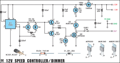
Therefore, the intensity of the light will be approximately 90% of its undimmed level. The easiest way to achieve this high frequency switching is to use a 555 timer integrated circuit (IC) - one of the commonest and most versatile ICs ever created. The circuit shown below (from the following article: Pulse Width Modulator with NE555 Timer Oscillator ) is designed to be used as a dimmer for 12V DC light bulbs or a speed controller for a 12V DC motor.
In our test circuit, the resistors in the LED strings were chosen to provide a forward current of 25mA to the LEDs. With three equal strings, the total current was 75mA and so we chose a transistor (BC547) with an Ic rating of 200mA - better safe than sorry.
This dimmer circuit cannot be used to turn the LEDs all the way off or to full brightness. In fact it operates within a duty cycle range of 5%-95% as the potentiometer (labelled P1) is turned from minimum to maximum. (By using germanium diodes in place of the two IN4148 signal diodes this dimming range can be extended to go from 1%-99%.
) While it is possible to build nice dimmers with simple components as shown above, for flexibility, speed, and ease of development, a microcontroller is often a better option. There are many different microcontrollers on the market which are very easy to programme, cheap to buy, and can be built into circuits with only a few external components required.
They make it possible to very rapidly try out different things to see what works without having to make physical changes to the circuit board. For microcontr 🔗 External reference
Related Circuits
This versatile circuit functions as a speed controller for a 12V motor with a continuous rating of up to 5A or as a dimmer for a 12V halogen or standard incandescent lamp with a maximum rating of 50W. It...
An AC mains operated single LED flasher circuit is designed using the widely used CMOS timer chip TLC555. The entire circuit is powered directly by the grid supply of 230VAC through a capacitive potential divider and associated components. This LED...
Purchase a 1W white LED and utilize a mobile phone battery to create a small lamp. A lampshade can be made from a glass-like milky white plastic bottle. The LED emits light through a radiating plate, which has two...
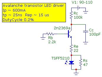
The speed of light has been measured using various methods. This note describes a method that is conceptually easy to understand and relatively simple to implement. The technique utilizes the time-of-flight optical pulse delay method, employing a short (20...
The wireless light switch circuit described here requires no physical contact for operating the appliance. You just need to move your hand between the infrared LED (IR LED1) and the phototransistor (T1). The infrared rays transmitted by IR LED1...
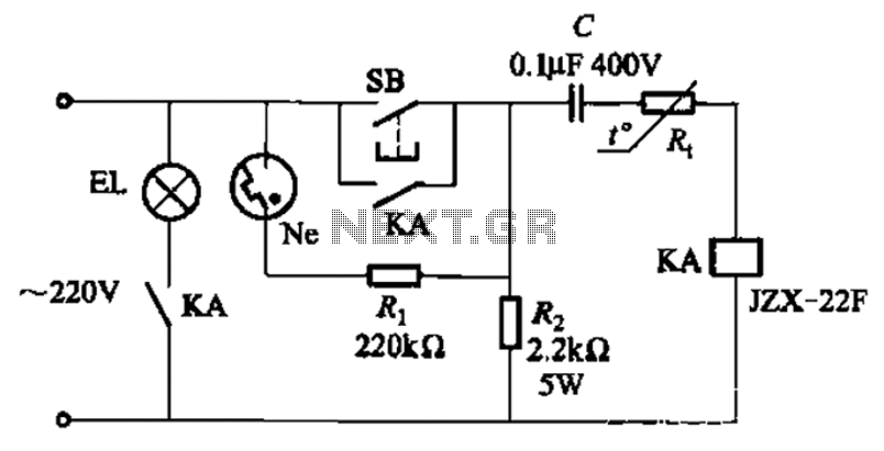
The circuit illustrated in Figure 2-49 is straightforward, featuring a cold Positive Temperature Coefficient (PTC) thermistor element. It utilizes the thermal resistance characteristics of the lamp to manage the delay time, which typically ranges from 10 to 30 seconds....