
Flashlights Finder Circuit using LM3909 Oscillator
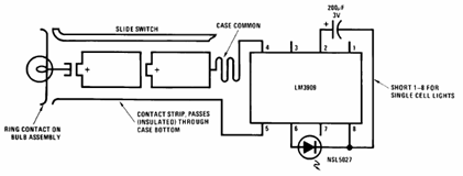
The Flashlight Finder circuit employs the LM3909 integrated circuit, which is capable of generating a series of pulses to drive LEDs. This circuit is particularly useful for locating a flashlight in low-light conditions. The LM3909 operates in a mode that allows it to alternate the LED's on and off states, creating a visual signal that can be easily spotted.
The circuit typically includes a few essential components: the LM3909 IC, a resistor, a capacitor, and one or more LEDs. The resistor is used to limit the current flowing through the LED, ensuring that it operates within safe limits. The capacitor is responsible for determining the flashing rate of the LED, which can be adjusted based on the desired frequency of the flashes.
In operation, when the circuit is powered, the LM3909 generates a square wave output that drives the LED. The frequency of this output can be modified by changing the values of the resistor and capacitor, allowing for customization of the flashing pattern. The circuit may also include a power source, such as batteries, which provide the necessary voltage for the LM3909 and the LED.
This design is particularly advantageous due to its low power consumption and simplicity, making it ideal for portable applications. The use of the LM3909 not only simplifies the design process but also enhances reliability, as it integrates the oscillator function within a single package. Overall, the Flashlight Finder circuit is a practical solution for enhancing visibility in situations where locating a flashlight quickly is crucial.What follows below is the schematic of Flashlight Finder circuit diagram using the LM3909, a monolithic oscillator designed to flash Light Emitting Diodes (LEDs) 🔗 External reference
Related Circuits

The circuit depicted in the figure operates within a frequency range of 400 to 850 MHz, designed as a UHF amplifying circuit. For optimal performance and results, it is recommended that the circuit be manufactured using silver-tin processing techniques. The...
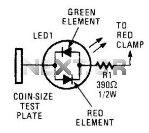
This circuit comprises a tri-color LED, a resistor, wire, and a coin-sized test plate. Two circuits must be constructed, one for each black clamp on a set of auto battery jumper cables. The circuits are installed inside the black...

The tuner is programmable via I²C-Bus and provides a FBAS signal at its output. There is also the homepage of Georg Acher containing information about this tuner. A control circuit has been developed for this tuner using the AT89C2051...

A simple low-power AM/FM radio receiver electronic project can be designed using the TA8122 integrated AM/FM receiver, manufactured by Toshiba Semiconductor. This radio receiver circuit is suitable for portable radio applications or other similar devices. The TA8122 radio receiver...

One example of the phase shift oscillator is the Bubba oscillator. This oscillator achieves a 45-degree phase shift for each section from a quad op-amp package. The Bubba oscillator is a type of phase shift oscillator that utilizes a...
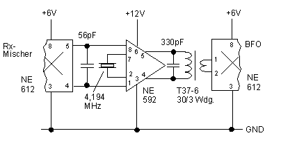
In this circuit, an NE592 acts as an IF amplifier. DC coupling between mixer and amplifier is practical because different +6 V and +12 V supply voltages are used. The voltage at the differential input is about 4.5 V....