
Capacitive Dimmer switch circuit
The capacitive dimmer switch circuit functions by leveraging the properties of capacitive reactance, which allows for the control of AC current flow to a load, in this case, a light bulb. The circuit includes a non-polar oil paper capacitor (C) that is connected in series with the light bulb. The switch (S) is a single-pole four-throw type, enabling the user to select different brightness levels by adjusting the dial.
In the maximum brightness setting, the circuit is complete without any capacitive interference, allowing full voltage to reach the light bulb. As the user rotates the dial to introduce the capacitor into the circuit, the capacitive reactance increases, which in turn reduces the effective voltage across the light bulb. The reduction in voltage leads to a decrease in light output, allowing for dimming functionality.
The circuit is designed to operate at a voltage rating of 100V, suitable for standard household lighting applications. The choice of a non-polar capacitor is critical, as it allows for AC operation without concern for polarity, ensuring reliable performance.
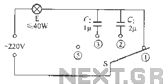
The dimmer circuit is particularly useful in applications where adjustable lighting is desired, such as in living rooms, theaters, and dining areas. By providing a smooth transition between brightness levels, it enhances the ambiance and user experience. The simplicity of the design, combined with the effectiveness of capacitive reactance, makes this circuit a practical solution for modern lighting control.Capacitive dimmer switch circuit shown in Figure 9. It is the use of capacitive reactance principle of alternating pairs made. S When the position shown, normal light bulb E, namely the maximum brightness; when dial to position when Gushan string into 2VF capacitor C. Lamp brightness decreases E; when the time is set aside to busy , solid C, <e. , Larger capacitance, reduce the brightness of the fork of a small block; when the dial to position , light E off.
c. , C Gallery using voltage 100V to f nonpolar oil paper capacitor, S to l 4 single-pole four-throw switch.
Related Circuits
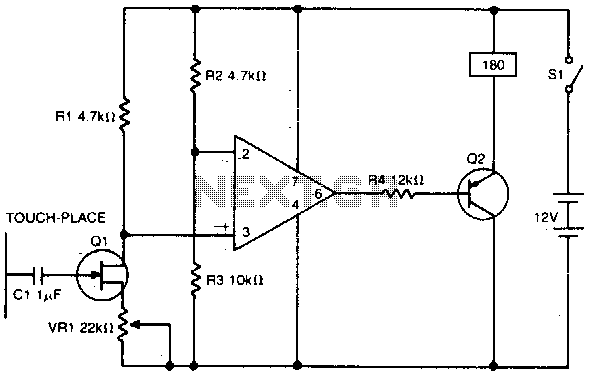
A high impedance input is provided by Q1, a general-purpose field effect transistor. The 741 operational amplifier is utilized as a sensitive voltage level switch, which subsequently activates Q2, a medium current PNP bipolar transistor. This action energizes a...
A 1200 Watt lamp dimmer circuit is designed to control lighting levels and is capable of managing up to 1200 Watts. This circuit utilizes the Q4015LT, which combines a Diac and a Triac for 230V dimming applications. It serves...
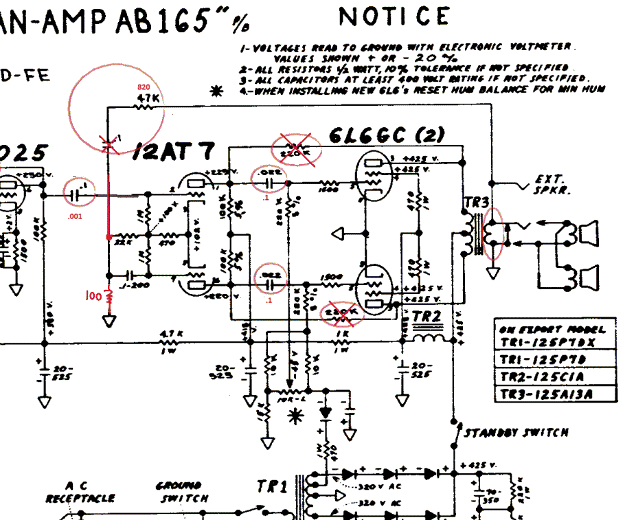
The Fender Bassman is a legendary guitar amplifier recognized by both guitar and bass players. Introduced in 1951, it was primarily aimed at bass guitar players and marketed as a bass amplifier for the Fender Precision Bass guitar, the...
A DC motor reversing circuit using non-latching push button switches. Relays control forward, stop, and reverse action, and the motor cannot be switched from forward to reverse unless the stop switch is pressed first. The described circuit employs a system...
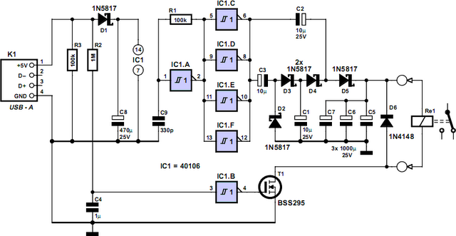
How often does it happen that a user shuts down Windows and then forgets to turn off the computer? This circuit automates that process. After Windows is shut down, a click occurs a second later, disconnecting the PC from...
A unit that is often very useful for isolating two stages in sound circuits. This circuit incorporates an amplification unit with a gain of X1. It employs only local negative feedback rather than total negative feedback, resulting in very...