
Computer Off Switch
This circuit serves as an automated shutdown mechanism for personal computers, ensuring that the power supply is disconnected shortly after the operating system is closed. The design incorporates a square wave oscillator to generate the necessary signals for driving the inverters, which subsequently power the voltage multiplier. This multiplier is essential for achieving the required voltage to operate the relay that disconnects the mains supply.
The choice of a 5 V supply voltage simplifies integration with existing USB power sources, making it versatile for various applications. The use of capacitors as a buffer allows for a brief delay in power disconnection, ensuring that the circuit can operate reliably even if the power supply voltage fluctuates momentarily during shutdown.
Safety considerations are paramount when working with mains voltage. The design mandates that sufficient spacing be maintained between high-voltage and low-voltage conductors to prevent accidental short circuits or electric shocks. The use of heat shrink tubing for insulation further enhances the safety of the assembly, protecting against potential hazards.
Overall, this circuit represents an efficient and practical solution for automating the power-off process of a computer system, minimizing the risk of leaving the device powered on unintentionally.How often does it happen that you close down Windows and then forget to turn off the computer This circuit does that automatically. After Windows is shut down there is a click` a second later and the PC is disconnected from the mains.
Surprisingly enough, this switch fits in some older computer cases. If the circuit doesn`t fit then it will have to be housed in a separate enclosure. That is why a supply voltage of 5 V was selected. This voltage can be obtained from a USB port when the circuit has to be on the outside of the PC case. It is best to solder the mains wires straight onto the switch and to insulate them with heat shrink sleeving.
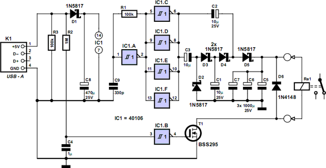
C8 is charged via D1. This is how the power supply voltage for IC1 is obtained. A square wave oscillator is built around IC1a, R1 and C9, which drives inverters IC1c to f. The frequency is about 50 kHz. The four inverters in parallel power the voltage multiplier, which has a multiplication of 3, and is built from C1 to C3 and D2 to D5. This is used to charge C5 to C7 to a voltage of about 9 V. The generated voltage is clearly lower than the theoretical 3x4. 8=14. 4 V, because some voltage is lost across the PN-junctions of the diodes. C5 to C7 form the buffer that powers the coil of the switch when switching off. The capacitors charge up in about two seconds after switching on. The circuit is now ready for use. When Windows is closed down, the 5-V power supply voltage disappears. C4 is discharged via R2 and this results in a 0` at the input of inverter IC1b. The output then becomes a 1`, which causes T1 to turn on. A voltage is now applied to the coil in the mains switch and the power supply of the PC is turned off.
T1 is a type BSS295 because the resistance of the coil is only 24R. When the PC is switched on, the circuit draws a peak current of about 200 mA, after which the current consumption drops to about 300 µA. The current when switching on could be higher because this is strongly dependent on the characteristics of the 5-V power supply and the supply rails in the PC.
There isn`t much to say about the construction of the circuit itself. The only things to take care with are the mains wires to the switch. The mains voltage may not appear at the connections to the coil. That is why there has to be a distance of at least 6 mm between the conductors that are connected to the mains and the conductors that are connected to the low-voltage part of the circuit. 🔗 External reference
Related Circuits
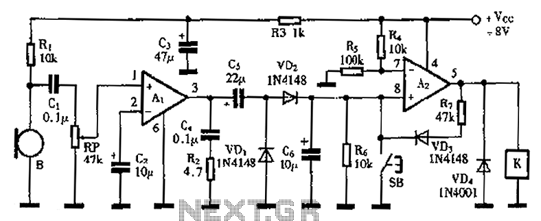
A practical voice-activated switch is presented. An A1 amplifier is connected to a conventional microphone (B) that picks up the audio control signal, which is then amplified. After amplification, the signal passes through components C5, VD1, and VD2, forming...
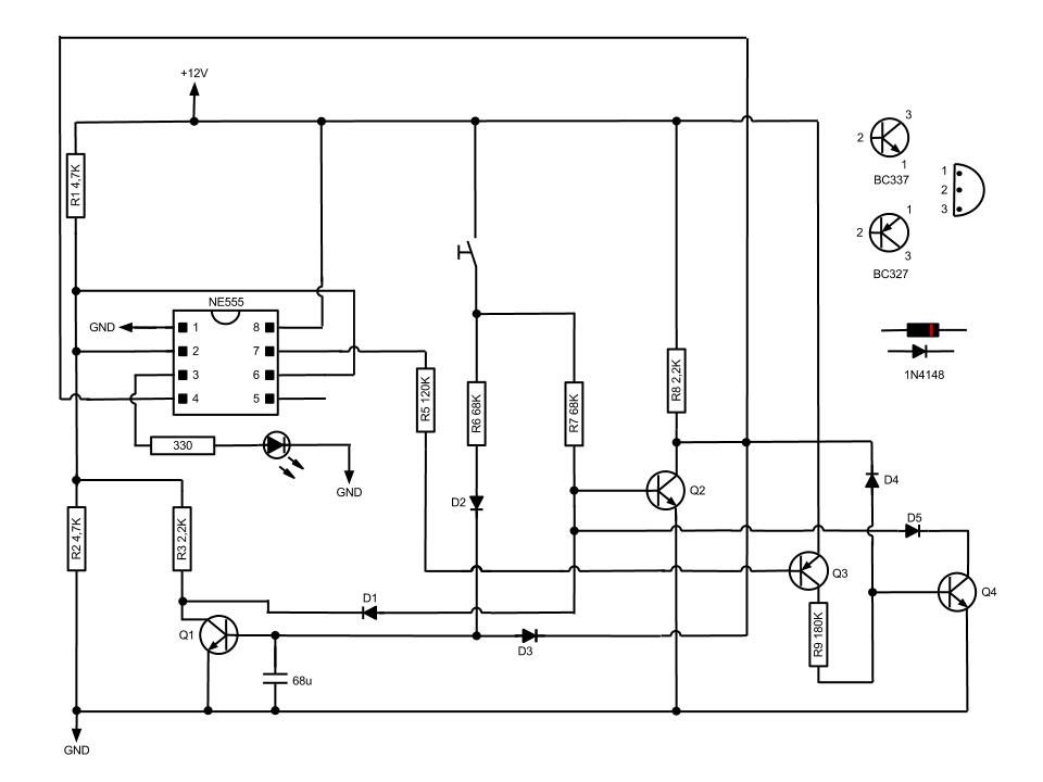
This circuit, based on the NE555 timer IC, toggles the output on and off using a momentary switch. It functions similarly to a mechanical latching relay but resets to its initial state when the power supply is turned off....
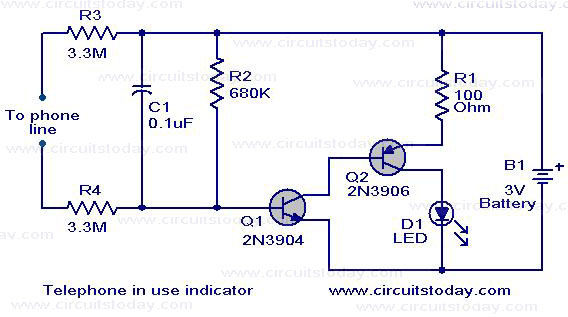
The circuit shown here serves as an indicator for when a telephone receiver is off-hook. It can be integrated with older telephone models that lack this feature. The circuit employs a complementary Darlington pair consisting of Q1 (2N3904) and...
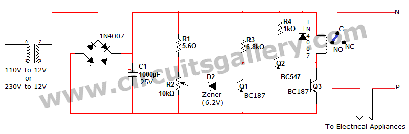
Voltage fluctuation is a significant concern in residential settings. For various reasons, the supply voltage may exceed 110V or 230V. This excessive voltage can potentially damage household electrical devices. An effective solution for electrical protection is the implementation of...
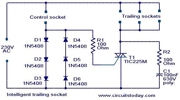
This circuit is a straightforward yet effective design where devices connected to the trailing sockets will operate only when the device connected to the control socket is powered on. For instance, if a motor is connected to the control...
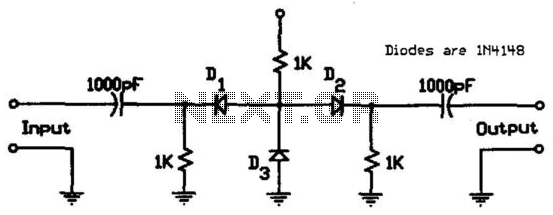
This circuit utilizes low-cost IN4148 diodes and demonstrates approximately 1.5 dB insertion loss across the frequency range of 10 to 1000 MHz with a few volts of negative bias. Under these conditions, diode D3 conducts while diodes D1 and...