
Capacitive liquid level sensor circuit
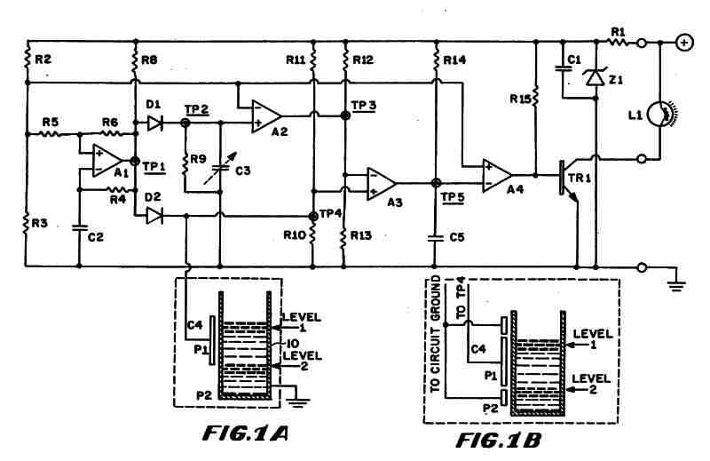
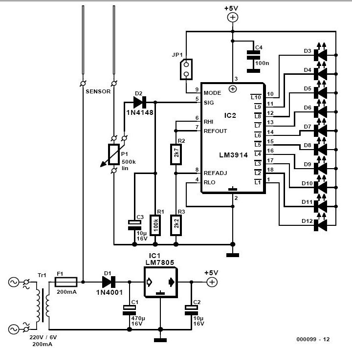
The output from the square-wave oscillator is illustrated as the square wave in Figure 2 (A). The oscillator generates an alternating electrical output that charges capacitors C3 and C4 through diodes D1 and D2, respectively. Capacitor C4 acts as the sensor capacitor, while capacitor C3 serves as the reference capacitor. Capacitor C4 consists of two conductive surfaces: plate P1 and the residual ground of receptacle 10 via its mounting arrangement. The fluid within receptacle 10 acts as the dielectric for the capacitor, causing the capacitance value of C4 to fluctuate in accordance with the fluid level. The capacitance of capacitor C3 is adjustable to align with the capacitance of capacitor C4 when a predetermined liquid level is detected, specifically at the critical level. Figure 1B illustrates an alternative embodiment of the design, where plates P2 and P3 are incorporated into the configuration of sensing capacitor C4. Plates P2 and P3 are connected to circuit ground, creating a lower level capacitance between plates P1 and P2, and an upper level capacitance between plates P1 and P3. When the voltage from the oscillator circuit at test point 1 (TP1) transitions from positive to negative, capacitors C3 and C4 begin to discharge through resistors R9 and R10, respectively. The circuit determines whether there is adequate fluid in receptacle 10 by measuring the difference in voltage decay across resistors R9 and R10, which is influenced by the capacitance values of capacitors C3 and C4.
The fluid level detector circuit operates effectively by utilizing a combination of analog components to create a reliable sensing mechanism. The use of a voltage regulator ensures that the circuit receives a stable voltage supply, critical for consistent performance. The square wave oscillator generates an alternating signal that is essential for the charging and discharging of the capacitors, which are integral to the sensing functionality. By adjusting the capacitance of capacitor C3, the system can be calibrated to respond accurately to specific fluid levels, enhancing the precision of the detection process.
The design's flexibility is further highlighted by the alternative embodiment that incorporates additional plates to modify the capacitance characteristics, allowing for more nuanced fluid level measurements. The incorporation of resistors R9 and R10 provides a straightforward means to assess the fluid level by monitoring the discharge rates of the capacitors. This arrangement not only simplifies the detection mechanism but also enhances the reliability of the readings, making this fluid level detector a practical solution for various applications where monitoring fluid levels is essential. Overall, the circuit exemplifies a well-thought-out approach to fluid detection, combining efficiency and adaptability in its design.FIG. 1 (A) illustrates the circuit diagram of one embodiment of the fluid level detector of the present design. The supply voltage for this circuit is typically provided by a 12-volt automobile battery which is reduced to a 5-volt DC source voltage by means of a voltage regulator comprising the combination of resistor R1 and zener diode Z1.
Capacitor C1 serves as a filter for this voltage supply regulator. The detector of FIG. 1A incorporates an amplifier A1 in conjunction with a resistor/capacitor network R4 and C2 and resistors R5 and R6 to form a square wave oscillator. A reference voltage is supplied from the voltage regulator where the reference voltage value is determined by the voltage divider circuit R2/R3.
This voltage serves as a reference voltage for the square wave oscillator and voltage comparators A2, A4 located in the circuit, as will be described. The output of the square-wave oscillator described above, is shown as the square wave of FIG. 2 (A). The oscillator produces an alternating electrical output which causes capacitors C3 and C4 to charge through diodes D1 and D2, respectively, where capacitor C4 is a sensor capacitor and capacitor C3 is a reference capacitor. As stated, capacitor C4 is the sensor capacitor wherein the two conductive surfaces of the capacitor are plate P1 and the residual ground of the receptacle 10 through its mounting arrangement.
The dielectric of the capacitor is the fluid in the receptacle 10 such that the capacitance value of C4 varies relative to the fluid level in the receptacle. The capacitance value of capacitor C3 is adjustable to match the value of capacitor C4 when a predetermined liquid level is sensed, i.e., at the critical level.
FIG. 1B shows an alternative embodiment of the present design wherein plates P2 and P3 are added to the configuration of sensing capacitor C4. The plates P2 and P3 are connected to circuit ground. A lower level capacitance is provided by plates P1 and P2, and an upper level capacitance is provided by plates P1 and P3.
When the voltage from the oscillator circuit at test point 1 (TP1) makes a transition from positive to negative, capacitors C3 and C4 begin to discharge through resistors R9 and R10, respectively. It is the difference in voltage decay across resistors R9 and R10 due to the capacitance values of capacitors C3 and C4 which enables the circuit to determine if there is sufficient fluid in the receptacle 10.
🔗 External reference
Related Circuits
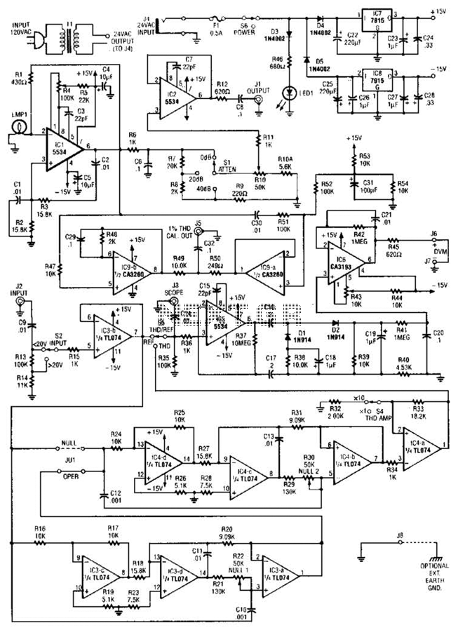
The circuit comprises a low-distortion, 1-kHz oscillator designed to measure Total Harmonic Distortion (THD) at a user-selected voltage level, suitable for voltage amplifiers or for testing amplifiers with power levels up to 600 W. It is capable of detecting...
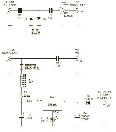
This wideband amplifier circuit is designed using the MAR-6 IC manufactured by Mini Circuits. The MAR-6 VHF-UHF wideband amplifier circuit provides a stable gain of at least 9 dB up to 2 GHz. Since the MAR-6 is designed to...
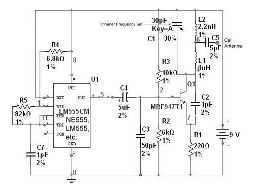
A cell phone jammer is an electronic device designed to obstruct the transmission of signals between a cell phone and its nearby base station. By transmitting on the same frequency as cell phones, the jammer generates significant interference, disrupting...
The PWM circuit is causing the inverter's current consumption to reach a dangerous level of 14 Amps. A potential solution involves reducing the drive voltage to the gates of the MOSFETs by controlling the base voltage of the buffer...
For individuals who prefer not to engage directly with soil, this simple soil moisture tester efficiently assesses the condition of their plants and the level of care they require. The soil moisture tester is a device designed to measure the...
The following circuit illustrates a Water Level Detector Circuit Diagram. This circuit is based on the PIC12F683 microcontroller. Features include the ability of the PIC microcontroller to enter a sleep mode. The Water Level Detector Circuit utilizing the PIC12F683 microcontroller...
Warning: include(partials/cookie-banner.php): Failed to open stream: Permission denied in /var/www/html/nextgr/view-circuit.php on line 713
Warning: include(): Failed opening 'partials/cookie-banner.php' for inclusion (include_path='.:/usr/share/php') in /var/www/html/nextgr/view-circuit.php on line 713