
Soil Moisture Tester Circuit
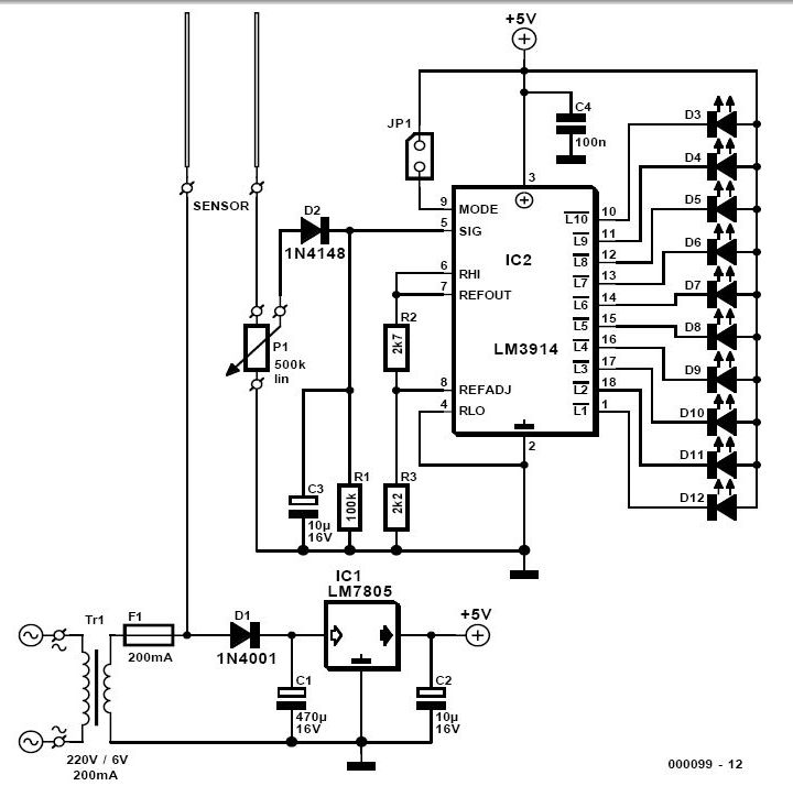
The soil moisture tester is a device designed to measure the moisture content in the soil, providing users with an indication of the hydration needs of their plants. The circuit typically consists of a moisture sensor, a microcontroller, and a display unit.
The moisture sensor is usually a resistive or capacitive type. In a resistive sensor, two metal probes are inserted into the soil. The resistance between these probes changes with the moisture level; as the soil becomes drier, the resistance increases. Conversely, a capacitive sensor measures the dielectric constant of the soil, which varies with moisture content. Capacitive sensors are generally more durable and less prone to corrosion compared to resistive ones.
The microcontroller processes the readings from the moisture sensor. It converts the analog signal from the sensor into a digital value that can be interpreted. This microcontroller can be programmed to set thresholds for moisture levels, allowing it to trigger alerts when the soil is too dry or too wet.
The display unit, which can be an LCD or LED, shows the moisture level in real-time. Some advanced models may include a graphical interface that provides additional information, such as optimal moisture levels for specific plants.
Power for the device can be supplied by batteries or an external power source, depending on the design. To enhance usability, features such as a low battery indicator or a calibration option for different soil types may be included.
Overall, the soil moisture tester is a practical tool for gardeners and plant enthusiasts, enabling them to maintain optimal plant health without the need for direct soil contact.For those of us who don t like to get their hands dirty, this simple soil moisture tester quickly checks the state of their plants and how much attention t.. 🔗 External reference
Related Circuits
Radio-Circuits has elevated the standard with this website. Unlike any other circuit site on the internet, they have compiled ten of the most popular FM transmitter circuits. Radio-Circuits provides a comprehensive collection of FM transmitter circuits, showcasing a variety of...
A sensitive and reliable RF field strength meter is an invaluable instrument in amateur radio and radio-controlled model applications. This field strength meter is utilized to align antennas for optimal gain and to determine the transmission range of radio...
This is a straightforward tester designed to verify the fundamental operations of an infrared remote control unit. It is cost-effective and simple to assemble. The tester utilizes the infrared receiver module TSOP1738. The operation of the remote control is...
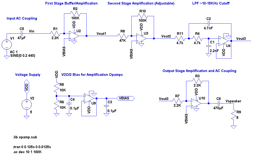
A video showcases a friend, James, playing his electric guitar, connected through an audio echo effect system to an amplifier. The echo effect is implemented on a breadboard rather than through hidden pedals or amp options. Apologies are made...
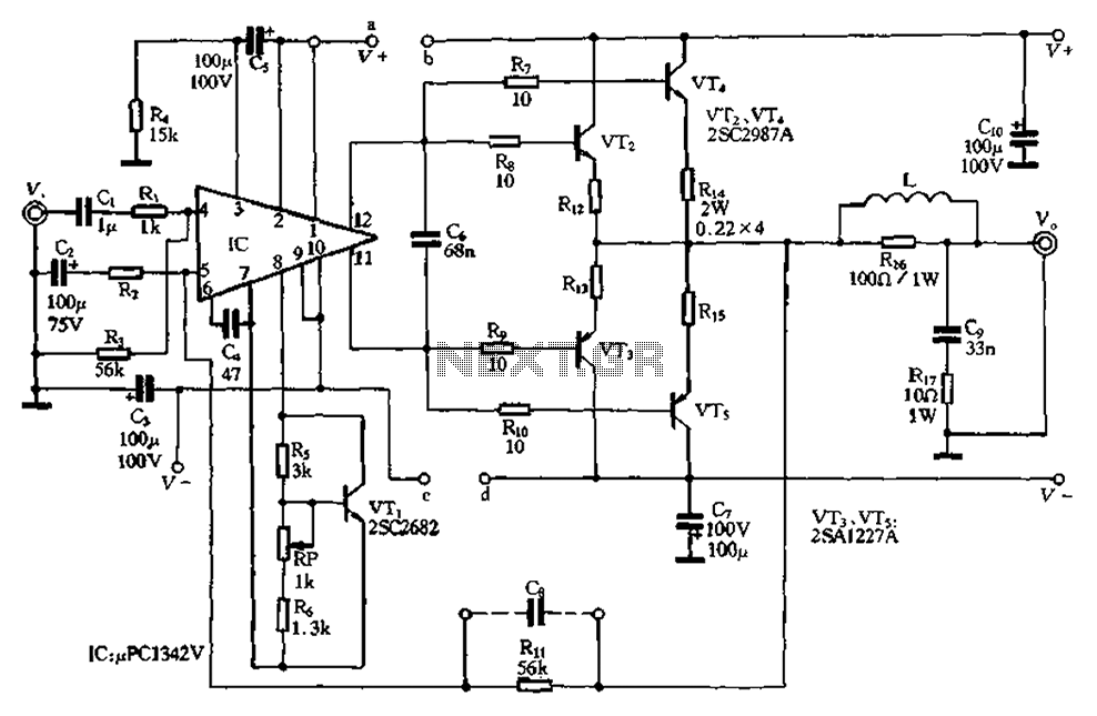
The pLPC1342V and NE are two companies involved in a tube amplifier circuit utilizing 2SA1227A and 2SC2987A transistors, achieving a maximum output power of up to 120W with a cutoff frequency of up to 500 MHz. The circuit, illustrated...
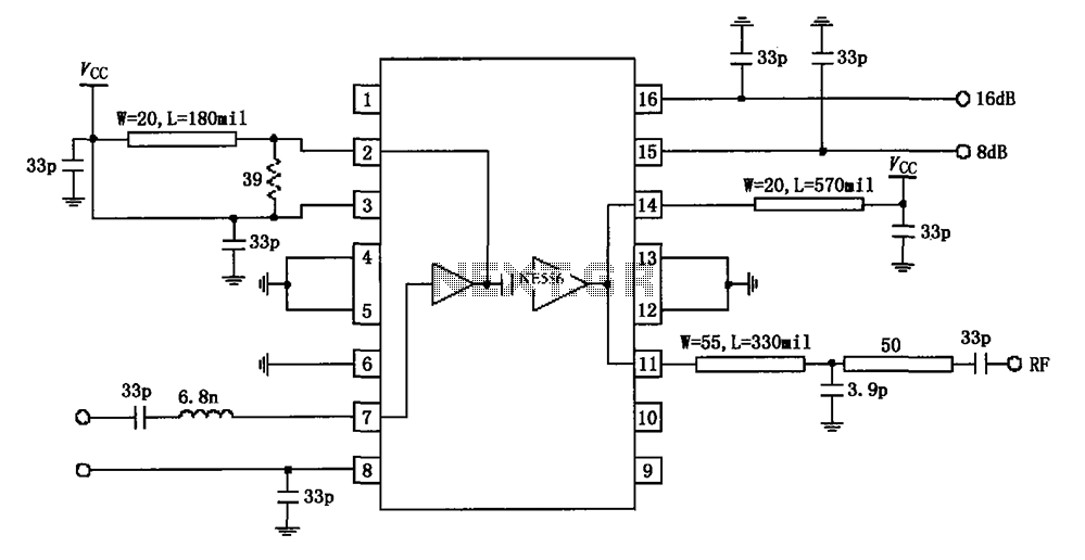
The circuit diagram illustrates the application of a 915MHz RF2155 power amplifier. The radio frequency (RF) signal enters through pin 7, where it is processed by a preamplifier. The output from the preamplifier is further amplified by the power...