
MAR-6 VHF-UHF wide band amplifier circuit design electronic project

The MAR-6 wideband amplifier circuit utilizes a single MAR-6 integrated circuit, which is optimized for high-frequency applications. The circuit is configured to amplify signals in the VHF and UHF ranges, making it ideal for applications such as television reception or RF signal processing. The stable gain of at least 9 dB ensures that the signal remains strong even at higher frequencies, thus enhancing the overall performance of the system.
Powering the MAR-6 through the signal output pin allows for a simplified design, eliminating the need for additional power supply circuitry. The operating voltage of approximately 3.5 V DC is low enough to be powered by common battery sources or small power adapters, making it versatile for various applications. The typical current consumption of around 16 mA ensures that the circuit remains energy-efficient.
The inclusion of an LED in the design serves as a power indicator, providing visual feedback when the circuit is operating correctly. The voltage measurement points outlined in the description are crucial for troubleshooting. If the LED fails to illuminate, checking the polarity of the DC input is essential, as incorrect wiring can lead to circuit malfunction. Additionally, ensuring that the LED is connected with the correct polarity is necessary for proper operation.
In summary, this wideband amplifier circuit is characterized by its compact design, efficient power usage, and robust performance across a wide frequency range, making it an excellent choice for applications requiring reliable signal amplification.This wide band amplifier circuit is designed using the MAR-6 IC manufactured by Mini Circuits. This MAR-6 VHF-UHF wide band amplifier circuit will providing stable gain of at least 9dB up to 2GHz. Because the MAR-6 is designed to receive its power via the signal output pin, it`s very suitable for use as a masthead amplifier.
It requires about 3. 5 V DC, at a working current of around 16mA. As you can see in the circuit diagram this masthead amplifier electronic project, require few external electronic parts, so if you will use SMD components you`ll have a very compact design. With power applied, the LED should glow reassuringly and you should be able to measure about 6. 8 - 7V DC at the end of R1 nearer IC2 and C5. If the LED doesn`t glow and you get no voltage reading, chances are that you`ve wired the DC input with reverse polarity.
If the LED doesn`t glow but there`s almost the full plug-pack voltage present at R1, you`ve almost certainly wired the LED in backwards. 🔗 External reference
Related Circuits
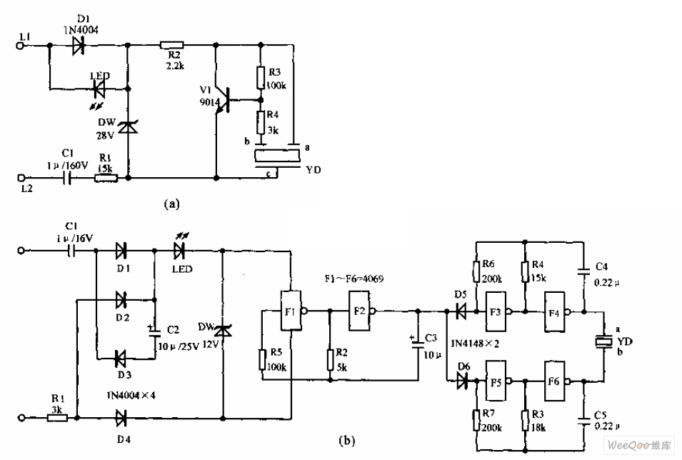
The telephone electronic ringer circuit is illustrated in the provided figure. It features an NPN transistor (either 9014 or 3DG12) as the primary component. The sound device, referred to as YD, functions as both a feedback device and is...
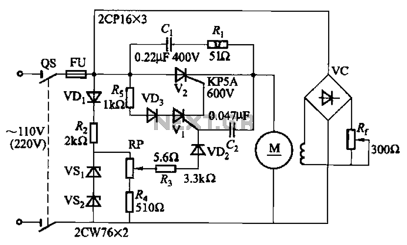
A 100W resistance-triggered motor control circuit designed for arc welding machines. It features an adjustment potentiometer (Rr) that can modify the DC motor excitation current. Additionally, a regulator (RP) is included to adjust the DC motor armature voltage, enabling...
This circuit activates an alarm whenever an object crosses the laser beam emitted by a laser. The output of the IC TL071 goes high when the laser beam is interrupted. This output voltage is further amplified by an NPN...
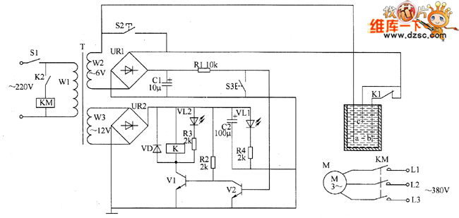
The liquid level controller circuit comprises a power supply circuit and a level detection control circuit, as illustrated in the accompanying chart. The power supply circuit includes a power switch (S1), a power transformer (T), bridge rectifiers (UR1, UR2),...
The electronic fishing shrimp machine circuit consists of an astable oscillator, an inverter circuit, and a high-voltage output circuit, as depicted in Figure 20. The astable oscillator circuit includes a time-base integrated circuit (IC), resistors R3 and R4, a...
The circuit was submitted by an individual from Newtownabbey, Northern Ireland. It has an exceptionally fast high frequency response, as demonstrated by applying a 100kHz squarewave to the input. All graphs were produced using Tina Pro. The circuit in question...