
capacity Computing Current from known Capacitance and Time to Charge to Known Voltage

In an electrical circuit involving a capacitor, the charging and discharging cycles can be analyzed to determine current characteristics. The capacitor, with capacitance C, stores energy when charged to a voltage V. The charge (Q) stored in the capacitor can be expressed as Q = C * V. During the charging phase, the capacitor receives a certain amount of charge over a defined time interval. The average current (I_avg) during this phase can be approximated using the formula:
I_avg = ΔQ / Δt
where ΔQ is the change in charge and Δt is the time taken for the change. For a capacitor charging from 0V to V, ΔQ is C * V, and if the charging occurs over a half-cycle (0.1 seconds for a 5 Hz frequency), then:
I_avg = (C * V) / (0.1 seconds)
This gives a rough estimate of the average current during the charging phase.
The discharging phase, where the capacitor releases its stored energy back to 0V, follows a similar approach. The average current during discharging will also be calculated over the same time interval, resulting in a similar formula.
It is crucial to differentiate between average current and RMS current (I_rms). The RMS current is a measure of the effective value of the varying current and is calculated over a complete cycle. For a sinusoidal waveform, the RMS current can be derived from the average current and the shape of the waveform. For a capacitor discharging and charging in a square wave manner, the RMS current can be calculated as:
I_rms = I_max / √2
where I_max is the peak current during either the charging or discharging phase.
In summary, while the average current provides a basic understanding of the capacitor's behavior during charge and discharge cycles, the RMS current offers a more comprehensive view of the effective current flowing through the circuit, especially when considering the waveform's characteristics.Assume a capacitor of capacity C is charging to voltage V and discharging to 0v at a rate of 5 times per second. How do I figure out the average current or what you might call RMS current I don`t need this to be exact - very rough approximation.
In general, the average current is equal to the change in charge divided by the time taken. But the change in charge is equal to the capacitance C multiplied by the change in voltage, which you know :- Your last paragraph is harder to address. The average current is not usually the same as the RMS current which will depend on the how the current varies with time. We would need to know how the charging/discharging takes place, for example constant current or through a constant resistance to a known voltage.
If you are cycling the charge/discharge process, the long-term average current will of course be zero but the RMS current will be non-zero. 🔗 External reference
Related Circuits
A 150 to 210 seconds analog delay timer project designed for controlling devices that require a minimum off timer before power can be restored, in order to prevent potential damage to the devices. This analog delay timer circuit can be...
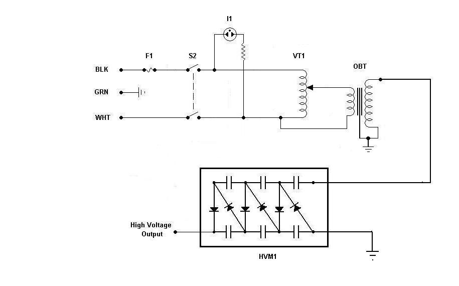
Using components from old microwave ovens, TV sets, and oil burners, it is possible to construct an economical instrument capable of producing high voltage outputs. The primary element in this setup is a voltage multiplier, which should be assembled...

Long-distance high-voltage direct current (HVDC) lines transmit hydroelectricity from Canada's Nelson River to a converter station, where it is converted to alternating current (AC) for use in southern Manitoba's electrical grid. HVDC systems utilize direct current for bulk power...

This series-feedback configuration of components provides a high input impedance and stable, wide-band gain video amplifier suitable for general-purpose applications. Below is the schematic representation of the circuit. The described video amplifier circuit employs a series-feedback topology, which is instrumental...
The two circuits demonstrate the process of opening a relay contact shortly after the ignition or light switch is turned off. The capacitor is charged, and the relay remains closed until the voltage at the diode anode reaches +12...
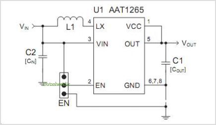
The AAT1275 evaluation board serves as a platform for testing and evaluating the AAT1275 switching boost converter equipped with a USB power switch. This evaluation board showcases the recommended size and placement of external components to achieve 5V output...