
Variable High Voltage Power Supply
This power supply is classified as high voltage and should not be used for standard household applications, which operate at low voltage (120 volts AC) and require high current (typically 200 Amps). The supply in question is low current (20 milliamps) and thus unsuitable for powering a house. For applications requiring a high voltage output of around 50 kV at 10 milliamps, modifications to the existing design may be necessary. A detailed schematic and component specifications would be beneficial for individuals seeking to build a variable power source capable of reaching 0-40 kV. Information regarding component values, names, and design considerations would be valuable for those unable to access existing documentation or schematics. There is potential for this setup to be adapted into a welding device capable of both constant current (CC) and constant voltage (CV) operation, possibly functioning as either an AC or DC power supply.With just a few parts from old microwave ovens, TV sets, and an oil burner, you can build an affordable instrument for whatever you wish to snap, crackle, or pop! The key component is the voltage multiplier, which I covered in the High Voltage Multiplier instructable.
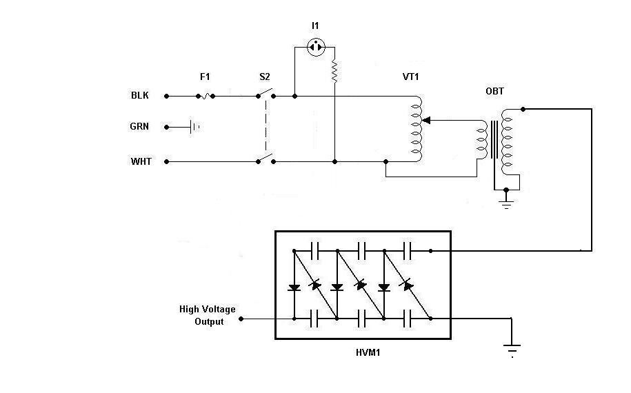
Build it first, then drop it into this project for a variable output. Mains voltage is applied to the power supply thru a 120 VAC Panel connector. With the case closed, current passes through a 5 Amp fuse, F1 and through the case safety switch, S1 causing the Ready indicator, I1 to light when the power switch S2 is placed in the ON position to energize the supply. Current passes through Variac, VT1 which adjusts the input voltage to the OBT. The OBT steps up the input voltage to a maximum of 6, 000 VAC. The output of the OBT is fed to the high voltage multiplier, HVM where it is multiplied to 51, 000 VDC output.
The case safety switch and the power contactor are not necessary for this supply to work. I thought the ability to power on and off by using a pushbutton was cool. Thats all. The second schematic shows them removed. My load has very high impedance so I need virtually no current (<< 1 mA) but I would like to reduce the ripple on the output so it is negligible. A simple RC low-pass filter with a resistor and a capacitor in series across the original output should do the trick. I don`t want to have to find a 100 kV cap so I`ll just join a few 20 kV caps in series to create a cap unit that will handle the voltage.
My new + output will come from the junction of the resistor and the + end of the caps (the low-pass filter output). Member Machine mentioned earlier that a front panel meter would be nice and I agree. He had some concerns about using a voltage divider so the meter could work with some reasonable voltage like 0 to 10 V instead of 0 to 50 kV.
I`ve done the resistor voltage divider thing successfully at 50 kV using a 5000:1 voltage divider. I then connected the divided voltage output to an analog DC voltmeter calibrated to 0 - 10 V. One final comment. I plan to use a 3PDT relay for K1 so the third pole can be used to discharge the HV output through an appropriately sized current limiting resistor. I plan to connect the HV output to one end of the resistor and the other end of the resistor to the common of the third pole on K1.
The NC contact of the third pole goes to ground. Whenever K1 is not energized, the HV output is routed to ground through the current limiting resistor. Sorry if this is a stupid thing to ask. but i dont have money for a variac, i was wondering if a 120vac light dimmer used in houses would work.
it says rated for 600 watts which would mean 5 amps right sooo would that work a reply would be great! is this really strong would this say power a house im looking for a very strong power supply for somthing im building wich requires as much power as a house maybe more lol This is a HIGH VOLTAGE power supply and cannot be used to power a house which is low voltage (120 volts AC).
This is also a low current supply (20 milliamps) and a house requires high current (200 Amps). So, no. This will not suit your needs. Hey, I`m looking for something on the scale of 50kv 10 milliamps. would i be able to adjust or modify this to get 10 milliamps any help would be appreciated Hi, I am needing to build a project of the variable power source 0-40kV can walk, I need if I you can send information to build the source as you did, since I can not download the pdf, you made me the source would come very well. please if you can send me information on the value of the component and the names and designing things.
any information will be very welcome i cant seem to get the image up so i`ll give you a URL to the burner I have a sneaking suspicion that this could be turned into some sort of a welding device (TIG or Spot). Possibly a device that was both CC and CV capable. Possibly ac/dc with cc/cv f 🔗 External reference
Related Circuits
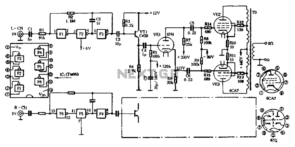
The CD4069 unit structure depicted in Figure 2-5 (a) consists of two abutment surfaces incorporated into a CMOSFET configuration. The input-output characteristics are illustrated in Figure 2-5 (b). Due to its superior unit switching curve, the CD4069 can be...
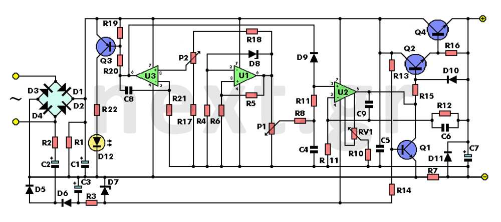
The left side of the circuit features the secondary winding of a 220V (primary) to 18V (secondary) / 3 Amp mains transformer. The 18V alternating voltage from the transformer’s secondary is rectified by diodes D1, D2, D3, and D4,...
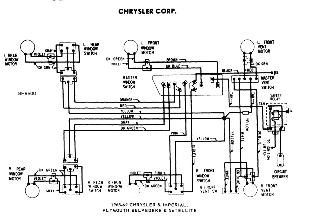
The power windows operate slowly, but connecting 12 volts directly to the motors allows them to function properly. A previous discussion mentioned using a common 5-pin ice cube relay, but there was no confirmation of its effectiveness. The power...
Many later radios utilize four 7-pin valves and require a high tension (HT) supply of 90V at approximately 12mA, and a low tension (LT) supply of either 125mA or 250mA, depending on the specific valves used. The original batteries...
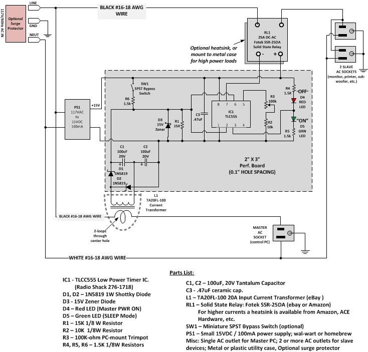
Most Apple and Windows PCs can enter "sleep" or "standby" mode when not in use instead of being completely shut down. This mode allows the operating system to restore all previous work sessions within seconds upon waking via keyboard...
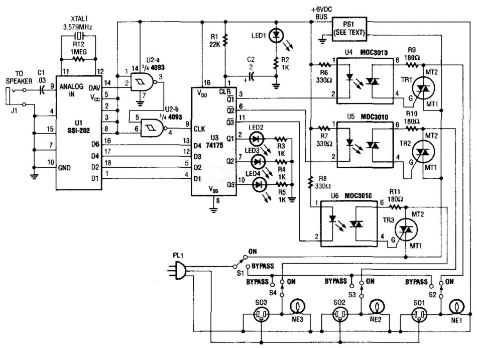
Tones from the DTMF on the telephone line are detected by U1. When a valid tone is received, pin 14 (D More: AV) of U1 produces a positive pulse that is used to drive NAND gates U2A and U2B,...
Warning: include(partials/cookie-banner.php): Failed to open stream: Permission denied in /var/www/html/nextgr/view-circuit.php on line 713
Warning: include(): Failed opening 'partials/cookie-banner.php' for inclusion (include_path='.:/usr/share/php') in /var/www/html/nextgr/view-circuit.php on line 713