
Car alarm circuit using 555 timer
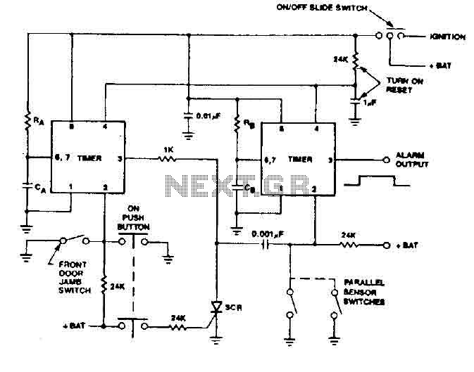
The 555 timer is a versatile integrated circuit commonly used in various timing, delay, pulse generation, and oscillator applications. In this context, the 555 timer is employed to create a delay mechanism that allows for the controlled deactivation of an alarm system. This feature is particularly important in security applications, where the integrity of the system must be maintained without exposing vulnerabilities.
The configuration of the 555 timer can be set up in either monostable or astable mode, depending on the desired functionality. In monostable mode, a single trigger pulse will produce a single output pulse of a defined duration, determined by external resistors and capacitors connected to the timer. This output pulse can be used to deactivate the alarm after a specified delay, providing a window for the driver to safely disengage the system.
Furthermore, the inclusion of a Remote Control System (RCS) enhances the security of the timer operation. The RCS is designed to prevent the triggering of timer B unless certain conditions are met. Specifically, it requires activation through detector switches that are strategically placed, ensuring that unauthorized attempts to trigger the timer are thwarted. This design minimizes the risk of false alarms and enhances the overall reliability of the alarm system.
In summary, the integration of the 555 timer with an RCS in this application not only facilitates a controlled delay for alarm deactivation but also reinforces the security of the system by employing strategic triggering mechanisms. This approach effectively mitigates vulnerabilities associated with external control switches, ensuring that the alarm system remains robust against tampering.555 timer produces a guaranteed delay, allowing the driver to deactivate the alarm and the elimination of a control switch vulnerable outside. The RCS prevents triggering a timer timer B, unless B is triggered by timer switches strategically located detector. 🔗 External reference
Related Circuits
Constantly changing light and sound analog controller circuit 02 The circuit described is an analog controller designed to modulate light and sound in a dynamic manner. It typically utilizes components such as operational amplifiers, resistors, capacitors, and transistors to achieve...
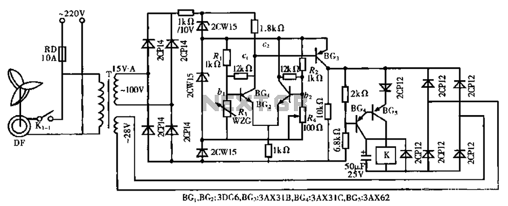
The circuit is a bistable circuit where each bistable unit is controlled by high and low output levels. When power is supplied to the circuit, current flows through components R13, CL, and VD to VD2 for full-wave rectification. The...
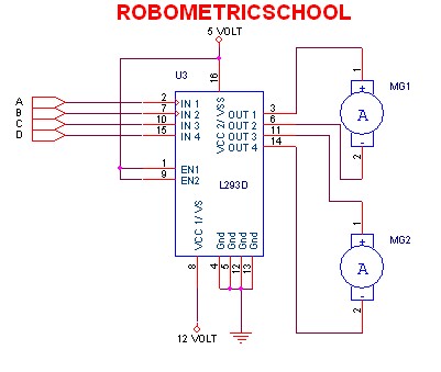
The electronic schematic of a DC motor driver using the L293D, as illustrated in Figure 2, enables the control of two DC motors continuously. It allows for one motor to rotate clockwise while the other rotates counterclockwise. Additionally, all...
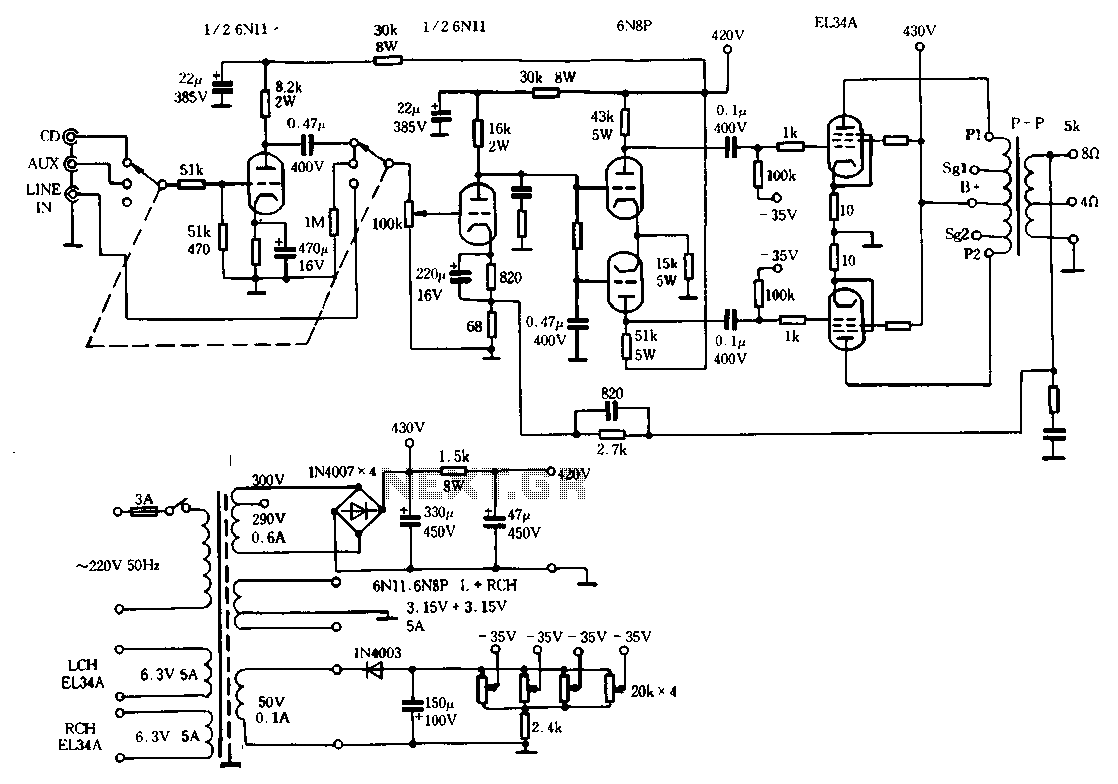
The Ml00 circuit is a typical tube circuit, functioning as a preamplifier. Its input stage utilizes a common cathode amplifier, followed by an inverter stage, culminating in a power amplifier that has been enhanced from a standard connection. This...
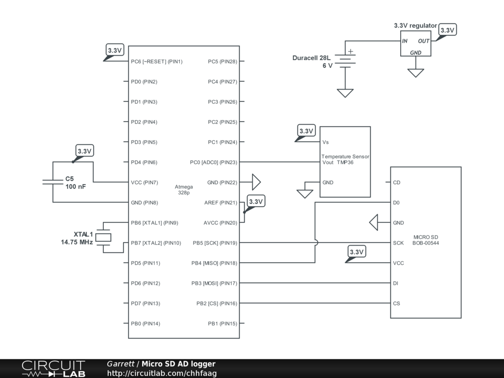
Read and write raw data from an SD card using a computer without a microprocessor, bypassing the FAT32 file system. The goal is to create a C script that can store specific parameters on the SD card for future...
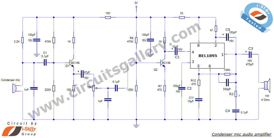
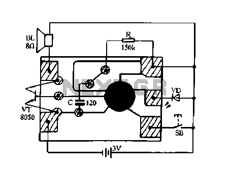
This document presents an audio amplifier circuit suitable for use in walkie-talkies, low-power transmitters, and packet radio receivers. The circuit utilizes a condenser microphone audio amplifier that delivers high-quality audio output of 0.5 watts at 3 volts. The design...
Warning: include(partials/cookie-banner.php): Failed to open stream: Permission denied in /var/www/html/nextgr/view-circuit.php on line 713
Warning: include(): Failed opening 'partials/cookie-banner.php' for inclusion (include_path='.:/usr/share/php') in /var/www/html/nextgr/view-circuit.php on line 713