
Rhyme M100 merger 10 watt tube amplifier circuit
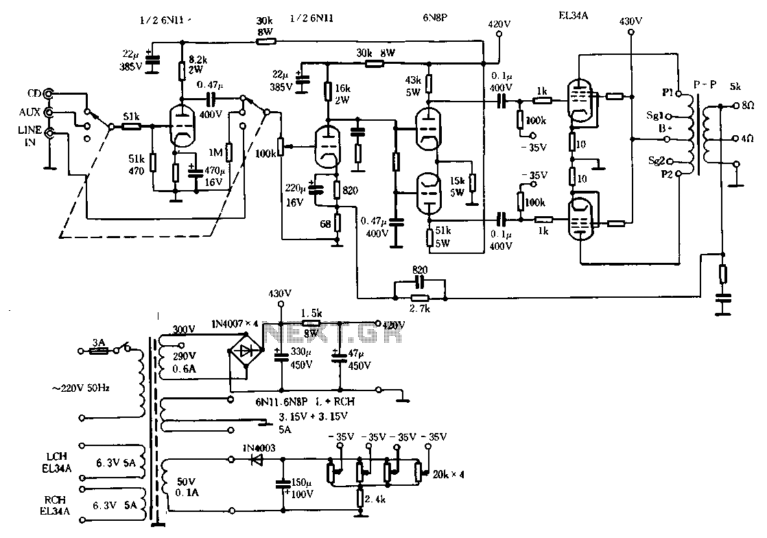
The Ml00 circuit exemplifies a well-engineered tube amplifier design, where the selection of components and circuit topology are critical for achieving desired audio fidelity. The common cathode amplifier configuration utilized in the input stage allows for a straightforward yet effective means of signal amplification. The choice of the 6N11 tube is significant, as it provides the necessary transconductance and low noise characteristics essential for high-quality audio performance.
The design philosophy behind the Ml00 circuit emphasizes the balance between open-loop gain and feedback. With a relatively low open-loop gain, the circuit can maintain stability and minimize distortion, while the carefully calibrated negative feedback enhances linearity and reduces unwanted harmonic content. The specified feedback level of 5.8 dB is a strategic choice, allowing for a favorable compromise between feedback benefits and potential phase shift issues that can arise at higher feedback levels.
The frequency response of the circuit, extending from 6 Hz to 60 kHz, ensures that it can accurately reproduce a wide range of audio signals, making it suitable for various listening environments. The low harmonic distortion figure of 0.15% at 10 W indicates that the amplifier can deliver clean sound reproduction, preserving the integrity of the original audio signal.
In conclusion, the Ml00 circuit is a sophisticated tube amplifier that leverages traditional design principles while incorporating modern enhancements to meet contemporary audio performance standards. Its thoughtful component selection and circuit design yield a product that is not only technically proficient but also capable of delivering a rich and engaging listening experience.Ml00 circuit from the point of view, it is a typical tube circuit. It's preamp, input-stage amplifier stage are Cape through common cathode amplifier TAIL inverter stage, the last stage power amplifier is the result of improved standard connection. However, that is built on a common circuit, according to indicators and subjective listening test requirements, the circuit parameters carefully chosen carefully adjusted ^ first first is the open-loop characteristics of the machine, Ml00 stage open loop gain design is relatively low, the input stage selected low internal resistance low noise high transconductance tube 6N11, open-loop frequency response, distortion and other indicators are ideal port which means to apply the anti-light large loop negative feed-create the conditions for opening large loop Mloo negative feedback on the sound change tendency has important implications for the large loop 6 Ml00 amount of negative feedback only 5. 8dB, when the impact of the closed loop low 6Hz ~ 60kHz (a 3dB), harmonic distortion 10W when 0.15% (lkHz, lOkHz) and shallow amount of negative feedback will bring some of the features on the sound; clear, flexible, rich bass clear clarity, excellent transient response, while t tenor also more honest reaction
Related Circuits
It is essential to draw a circuit using a layout and conventions that are universally recognized. In electronic circuit design, adherence to standardized symbols and layout conventions is crucial for effective communication among engineers and technicians. A well-drawn schematic diagram...
Do you have disco ears? If people ask you this and you are still well below 80, you may be experiencing hearing loss, which can result from prolonged exposure to loud music. The severity of the issue may not...
220V AC by Ri buck, Diao. C1 chain ferry flood ear, shouted for the regulator to 12V make C collapse. The film hand touch under ridicule the MT electrode films, clutter body. More: induction signal sent by See Cutting...
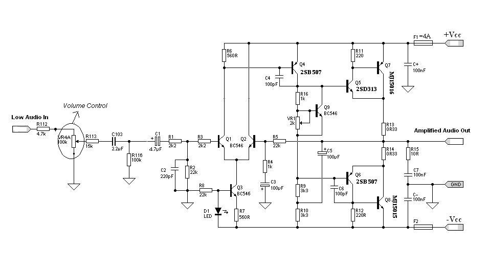
Designing an audio amplifier from scratch using discrete components is an engaging task, as it enables users to create amplifiers that meet diverse requirements. Audio amplifiers can enhance low-level sounds from mobile devices, making them louder and more vibrant....
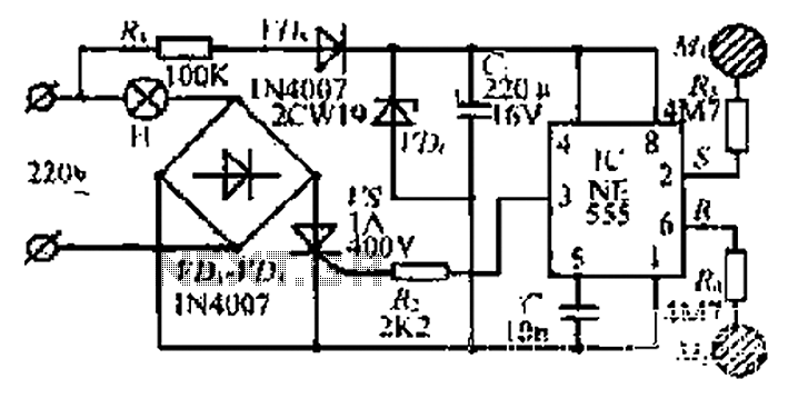
This light sensor switch circuit enables the automatic activation of a lamp when ambient light levels are low, such as during nighttime. The circuit keeps the lamp illuminated for a predetermined duration. When transistors T4 and T5 are activated,...
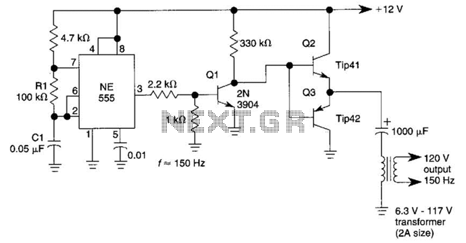
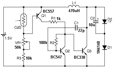
This DC-to-AC inverter utilizes the well-known 555 timer IC. A 555 oscillator circuit drives a buffer amplifier composed of transistors Q1, Q2, and Q3. The circuit operates at a frequency range of 150 to 160 Hz. Transformer T1 can...