
Electronic Circuit Schematic DC Motor Driver using L293D Dual H-Bridge
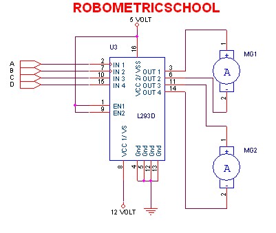
According to the guidance provided in Figure 3, the motor will rotate clockwise when a logic high (1) is applied to input A and a logic low (0) is applied to input B. Conversely, the motor will rotate counterclockwise when input A receives a logic low (0) and input B is set to a logic high (1). To stop all motors, a logic high (1) must be applied to all input pins. It is crucial to avoid applying a logic low (0) to all inputs simultaneously, as this can lead to errors or damage to the L293D, potentially resulting in overheating or short circuits.
The L293D is a dual H-bridge motor driver capable of controlling the direction and speed of DC motors. Each H-bridge can control one motor, allowing for independent operation of two motors. The device features built-in diodes for back EMF protection, which is essential for safeguarding the circuit from voltage spikes generated by the motors during operation.
To implement the circuit, the L293D is connected to the power supply, motors, and a microcontroller or other control logic. The control signals from the microcontroller dictate the state of the inputs A and B for each motor. By using PWM (Pulse Width Modulation) on the enable pins of the L293D, speed control can also be achieved, allowing for variable motor speeds in addition to directional control.
Proper heat dissipation measures should be considered, as the L293D can generate heat during operation, especially under high load conditions. Heat sinks may be necessary to maintain optimal operating temperatures and prevent thermal shutdown. Overall, the L293D motor driver is a versatile component for robotics and automation applications, providing efficient control of DC motors in various configurations.According electronic schematic of DC driver motor using L293D in figure 2, we can use it to control two DC motor continuously. We can control DC motor one to rotate clock wise and DC motor two to rotate anti clock wise. We also can control all motor to rotate clock wise, anti click wise, or stop all. We can control it with give control in input of L293D. You can use guidance like in figure 3 bellow: From figure 3 above, we can make motor rotate clock wise when in input we give 1 logic in A and 0 logic in B. Also we can make motor rotate anti clock wise when input we give 0 logic in A and 1 logic in B. We can stop all motor with give in all input 1 logic. Attention you don`t give in all input with 0 logic, because it can make L293D error or damage like burn or shot circuit.
So careful when you set it. Thank you very much for your visiting in Robometricschool blog, We hope you will get more information about Robotic, Mechatronic, and Electronic. And don`t forget to give us your comment about this article. Let keep for building comment. 🔗 External reference
Related Circuits
This 555 timer circuit toggles a relay when a button is pressed. Pins 2 and 6, the threshold and trigger inputs, are held at half the supply voltage by two 10K resistors. When the output is high, the capacitor...
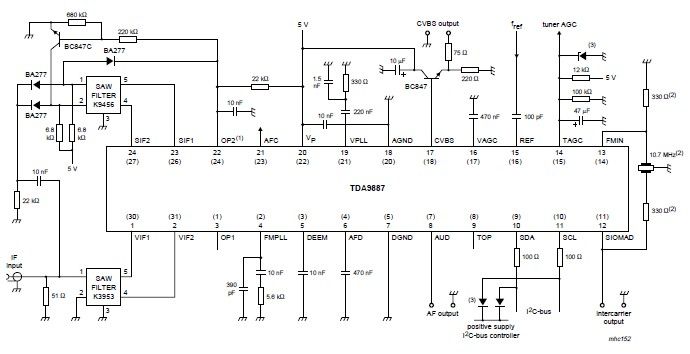
The integrated circuit (IC) is a multistandard vision and sound intermediate frequency (IF) phase-locked loop (PLL) demodulator that operates without the need for alignment. It supports multiple standards, including PAL, SECAM, and NTSC, and is capable of processing both...
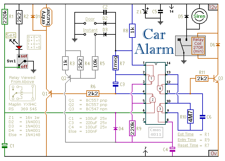
This circuit is designed to secure a vehicle at a low cost if constructed independently, making it more affordable than purchasing a commercial car alarm system. The alarm is activated by opening switch Sw1, which can be any small...
The micropower circuit automatically provides shutdown, power-up, and low-battery lockout functions without requiring software or operator control. The micropower circuit is designed to manage power efficiently in battery-operated devices, ensuring optimal functionality while conserving energy. The shutdown feature is activated...
The schematic diagram below illustrates a simple and cost-effective 12-volt DC 50W off-line SMPS (switched-mode power supply) circuit. It is suitable for DIY home projects or for learning about the operation of flyback converters. This power supply unit (PSU)...
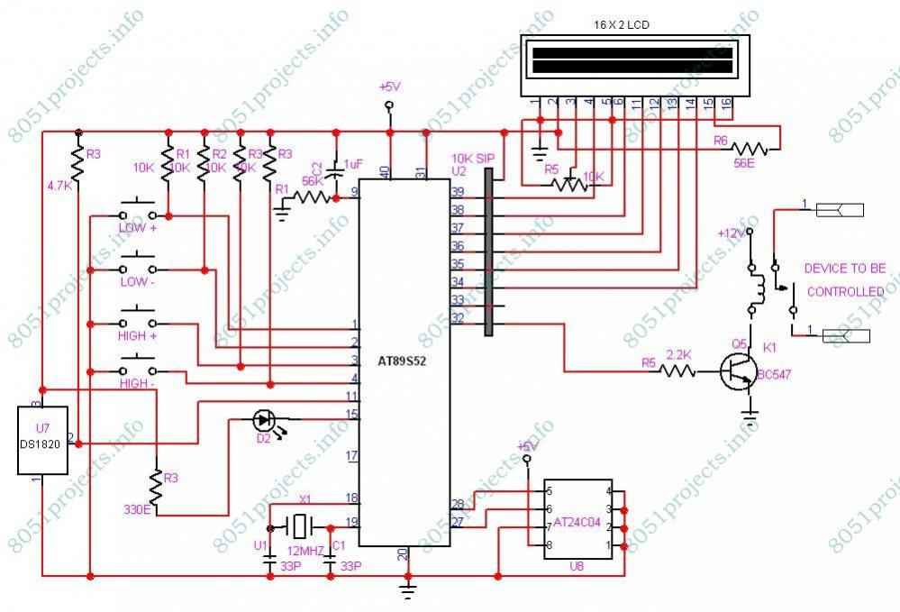
This project is designed to monitor and control temperature. The system utilizes the DS1820 temperature sensor to measure the temperature, which is then displayed on an LCD. It features two preset levels: a low preset and a high preset....