
Car Alarm With Horn As Loudspeaker

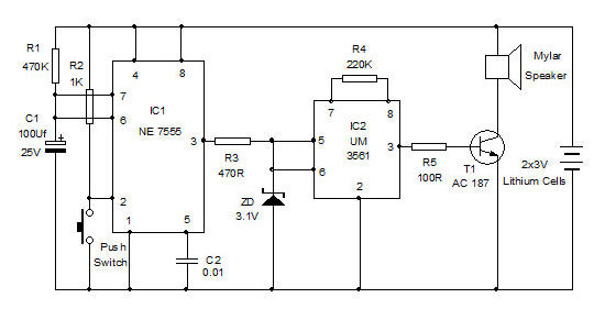
The described circuit employs a 555 timer in astable mode, which generates a square wave output. The frequency of the output can be adjusted by varying the resistors and capacitors connected to the timer. This output is fed into the base of the MJE34 transistor, which acts as a switch. When the timer outputs a high signal, the transistor is turned on, allowing current to flow from the power supply through the horn, causing it to produce sound.
The MJE34 transistor is chosen for its ability to handle higher currents, suitable for driving the horn. The use of a blocking diode, D4, serves to protect the circuit from back EMF generated by the inductive load of the horn when it is turned off. This diode ensures that the current flows in one direction, thus preventing damage to the 555 timer and the transistor.
To enhance the performance of this circuit, it is advisable to include a capacitor across the power supply terminals to filter out any noise and stabilize the voltage supply. Additionally, the frequency of the sound produced by the horn can be fine-tuned by adjusting the resistor-capacitor (RC) network connected to the 555 timer.
Overall, this circuit design effectively combines the functionalities of the 555 timer, a power transistor, and a blocking diode to create a reliable auto horn system. The simplicity of the design allows for easy implementation in automotive applications where audible alerts are necessary. An auto horn will work as a speaker of limited audio-frequency range. This circuit uses a 555 timer as a n oscillator to drive an MJE34 transistor, which in turn drives the horn. Normal horn operation is ensured by blocking diode D4.
Related Circuits
The core of this overheat detector circuit features a precision integrated temperature sensor, the LM35 (IC1). This sensor provides a linear and directly proportional output in millivolts over a temperature range of 0 to +155 degrees Celsius. The LM35...
20W Bridge Audio Amplifier kit, based on the TDA2005 IC, a class B dual audio amplifier, specifically designed for car radio applications etc. More: Power supply - 18 VDC Output power - 20 W, 4 Ω IC built in Thermal Shut-down,...
Personal Alarm Circuit Diagram. If you feel threatened or need urgent support in a crowd, use this alarm to catch the attention of others. The personal alarm circuit is designed to provide a loud audible signal when activated, serving as...
A 555 timer (U1) is configured as an astable multivibrator (oscillator) with a duty cycle of 400:1 and a frequency of 40 Hz. When power is applied to the circuit, capacitor C1 (connected to pin 6 of U1) is...
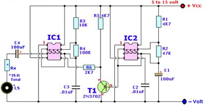
Browse home alarm circuit explanation latest schematic siren wailing with latest Wailing Alarm Siren circuit schematic with explanation. The loudspeaker LS and the resistor marked Rx should be together 75 ohms. If a standard 8-ohm speaker is used, then...
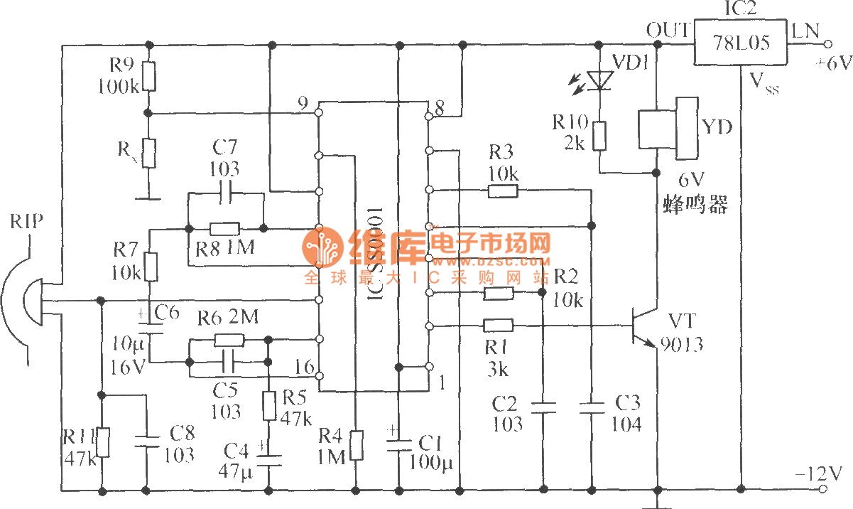
The human infrared thermal release alarm can detect the infrared radiation emitted by the human body at any time of the day or night, triggering both sound and light alarms. This device is particularly suitable for electronic security applications....