
overheat detector alarm lm35
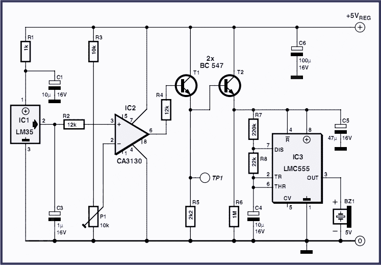
The overheat detector circuit is designed for reliable temperature monitoring and alerting in various applications, such as industrial equipment, home appliances, or automotive systems. The LM35 temperature sensor is chosen for its high accuracy and linearity, making it suitable for precise temperature measurements. The CA3130 op-amp comparator is utilized for its low input offset voltage and high gain, ensuring that even small changes in temperature can trigger the alarm system effectively.
The adjustable voltage divider formed by R3 and P1 allows users to set the trip point according to specific requirements, enhancing the circuit's versatility. The output from the comparator, when activated, not only drives the buzzer but also enables the subsequent transistor stages. Transistor T1 acts as a switch that controls the power to the oscillator circuit, while T2 ensures that the 555 timer operates reliably. The 555 timer in astable mode generates a continuous square wave, which is then converted into an audible sound by the piezoelectric buzzer. The timing components R7, R8, and C4 can be adjusted to modify the frequency and duration of the sound, allowing customization of the alert signal.
Furthermore, the circuit's design includes provisions for integrating a relay driver, making it adaptable for controlling larger loads. By replacing the piezo buzzer with a relay, the circuit can activate various high-power devices, providing a practical solution for alerting users in critical situations. This feature expands the usability of the overheat detector beyond simple auditory alerts, enabling it to serve as an integral part of a comprehensive safety system.At the heart of this over heat detector circuit is a precision integrated temperature sensor type LM35 (IC1), which provides an accurately linear and directly proportional output in mV, over the zero to +155 degrees C temperature range. The LM35 develops an output voltage of 10 mV/K change in measured temperature. Designed to draw a minimal curren t of its own, the LM35 has very low self heating in still air. Here the output of the LM35 is applied to the non-inverting input of a comparator wired around a CA3130 opamp (IC2). A voltage divider network R3-P1 sets the threshold voltage, at the inverting input of the opamp. The threshold voltage determines the adjustable temperature trip level at which the circuit is activated.
When the measured temperature exceeds the user-defined level, the comparator pulls its output High to approx. 2. 2 V causing transistor T1 to be forward biased instantly. T2 is also switched on, supplying the oscillator circuit around IC3 with sufficient voltage to start working.
The 555 set up in astable mode directly drives active piezoelectric buzzer Bz1 to raise a loud alert. Components R7, R8 and C4 determine the on/off rhythm of the sounder. A transistor based relay driver may be driven off the emitter of T1 (TP1). Similarly, replacing the piezo sounder with a suitable relay allows switching of high-power flashers, sirens or horns working on the AC mains supply.
🔗 External reference
Related Circuits

This is a simple metal detector utilizing a TDA2822 and several NPN transistors. An arrow indicates the signal flow direction from the Emitter of transistor T3 to the 10nF capacitor C4, which is opposite to the typical left-to-right flow...
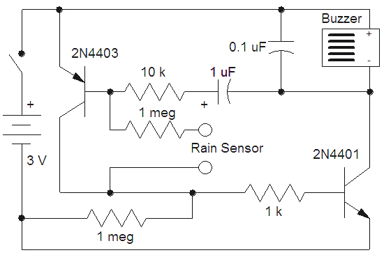
This rain detector alerts users immediately when it starts to rain, providing enough time to close windows and secure belongings. The battery-operated circuit consumes minimal current when the sensor is dry and maintains low current consumption when the buzzer...

The oscillator is a standard UHF design that delivers approximately 10 mW at a frequency of 1.2 GHz. Resistors R1 and R2 bias the base of transistor Q1 to 1.2 V through a 12-ohm resistor. The collector current is...

The circuit consists of a triggering device, a monostable delay circuit, an alarm sound generator, an audio amplifier circuit, and a light control circuit, with a partially blocking preset circuit and power circuit. When the door is locked and...

The gas sensor primarily consists of tin dioxide mounted on a ceramic substrate. The sensor's resistance changes based on the concentration of reducing gases present in the air. The depicted circuit is effective for detecting hazardous levels of combustible...
This electronic liquid detector circuit diagram is based on the ULN2429 monolithic bipolar integrated circuit designed for detecting the absence or presence of many different types of liquids. The ULN2429 electronic liquid detector circuit can be used in automotive,...