
Car BackUp Alarm

The described circuit utilizes the automobile's brake light system to control an alarm or notification system, ensuring that the alarm only sounds when necessary. The design typically incorporates a relay that is activated by the brake light switch. When the brake pedal is pressed, the circuit completes, allowing current to flow and energizing the relay. This action can trigger an alarm or other signaling device, alerting the driver or nearby individuals.
In a typical implementation, the circuit may include a diode in parallel with the relay coil to prevent back EMF from damaging other components when the relay is deactivated. A capacitor may also be added to smooth out the voltage changes, ensuring stable operation.
The circuit can be further enhanced by incorporating an adjustable timer, allowing for a delay in the alarm activation after the brake is released, which can be useful in scenarios where the driver may momentarily pause before moving.
Overall, while the circuit is based on older technology, its fundamental principles remain relevant. The simplicity and effectiveness of this design make it a reliable choice for applications requiring controlled alarm systems in automotive environments.The brake lights of the automobile trigger this circuit on and off. This save the annoyance of the alarm when it is not needed. This is an older circuit which was published in Popular Electronics Magazine, but still a good circuit today. 🔗 External reference
Related Circuits

This circuit is designed to secure a vehicle at a low cost if constructed independently, making it more affordable than purchasing a commercial car alarm system. The alarm is activated by opening switch Sw1, which can be any small...
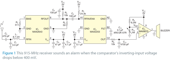
The receiver circuit in Figure 1 activates an audio alarm when the transmitter (Figure 2) moves beyond a specified perimeter. The transmitter functions as a voltage-controlled oscillator, operating at approximately 915 MHz within the unlicensed ISM (industrial/scientific/medical) band. It...
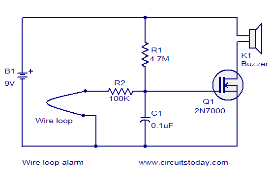
The circuit diagram illustrates a simple wire loop alarm utilizing an N-channel enhancement FET 2N700, a buzzer, and several passive components. Under normal conditions, the gate of the 2N700 (Q1) is connected to the ground through a 100K resistor...

The triangular wave circuit consists of two operational amplifiers (OPs). R62 serves as the offset adjustment, while R27 is utilized for peak adjustment. A switch is included to select different resistances, allowing for the generation of triangular waves at...
This simple circuit drives 6 LEDs in Knightrider scanner mode. Power consumption depends mainly on the type of LEDs used if you use a 7555 (555 CMOS version). More: Note that VDD and GND for the ICs are not...
This circuit utilizes the widely available LM3914 integrated circuit (IC). The IC is straightforward to operate, does not require external voltage regulators due to its built-in voltage regulation feature, and can be powered from nearly any voltage source. The LM3914...