Simple Alarm Circuit Keeps Wandering Children
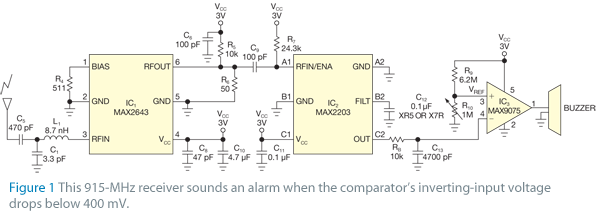
The receiver circuit in Figure 1 activates an audio alarm when the transmitter (Figure 2) moves beyond a specified perimeter. The transmitter functions as a voltage-controlled oscillator, operating at approximately 915 MHz within the unlicensed ISM (industrial/scientific/medical) band. It features a tuning voltage described by the equation 1.5V = 3G - R2/(R1 + R2), allowing frequency adjustments by varying the resistor values R1 and R2. The receiver circuit consists of a low-noise amplifier (IC1), a power detector (IC2), a comparator (IC3), and a buzzer. When the transmitter is within range—for instance, when carried by a child or pet—the receiver detects the RF signal and produces a voltage exceeding 400 mV at the inverting terminal of the comparator. Resistors R9 and R10 set the reference voltage at the comparator's non-inverting terminal, calculated as 3G - R10/(R9 + R10), keeping the comparator's output low. However, when the transmitter moves outside the designated boundary, the detected RF signal drops below 400 mV at the comparator. Consequently, the comparator generates an output of approximately 3V, activating the buzzer to signal that the transmitter has exceeded the restricted perimeter. To enhance detection range, additional low-noise amplifiers or variable-gain amplifiers (VGAs) can be placed before the power detector. Adjusting R10 allows for increasing or decreasing the desired perimeter by modifying the comparator's reference voltage.
The described circuit operates effectively within the ISM band, utilizing a voltage-controlled oscillator as the transmitter to send RF signals. The receiver circuit is designed to monitor the signal strength continuously. When the RF signal strength is adequate, indicated by a voltage above 400 mV at the comparator's inverting terminal, the alarm remains inactive, ensuring that the system does not trigger unnecessarily. The precise tuning of the transmitter's frequency is crucial for maintaining reliable communication between the transmitter and receiver, which is achieved through the adjustment of resistors R1 and R2.
The operational principle of the receiver is based on the comparison of the received signal strength against a set reference voltage. The use of resistors R9 and R10 for setting the reference voltage allows for customization of the system's sensitivity and perimeter range. The comparator, which is a critical component, effectively differentiates between acceptable and unacceptable signal levels, ensuring that the alarm is triggered only when the transmitter breaches the defined perimeter.
In scenarios requiring extended detection capabilities, the integration of additional low-noise amplifiers or VGAs can significantly improve the receiver's ability to detect weaker signals, thus increasing the operational range of the system. Adjustments to the reference voltage via R10 can tailor the system to specific applications, accommodating various perimeter requirements. Overall, this circuit serves as a practical solution for applications needing perimeter monitoring, such as child or pet tracking systems.The receiver circuit in Figure 1 sounds an audio alarm when the transmitter (Figure 2) moves beyond a designated perimeter. The transmitter, a voltage-controlled oscillator, operates at approximately 915 MHz in the unlicensed ISM (industrial/scientific/medical) band.
It has a tuning voltage of 1. 5V=3G—R2/(R1+R2), which lets you easily adjust the f requency by varying the values of resistors R1 and R2. The receiver comprises low-noise amplifier IC1, power detector IC2, comparator IC3, and a buzzer. When the transmitter is within range ”for example, when a child or a pet is carrying it ”the receiver detects the RF signal and provides a voltage greater than 400 mV at the inverting terminal of the comparator. Resistors R9 and R10 preset the reference voltage at the comparator`s noninverting terminal. The reference voltage is 3G—R10/(R9+R10), and the comparator`s output remains low. Circuit keeps wandering children and pets nearby figure 2When the transmitter moves outside the predetermined boundary, the detected RF produces less than 400 mV at the comparator.
The comparator then generates an output of approximately 3V, which turns on the buzzer and sounds an alert that the transmitter has moved beyond the restricted perimeter. To increase the detection range, you can place additional low-noise amplifiers or VGAs (variable-gain amplifiers) in front of the power detector.
You can also increase or decrease the desired perimeter by adjusting R10 to change the comparator`s reference voltage. Link 🔗 External reference
