
car battery charger schematics
The described circuit operates as a battery charger powered by an external power source. The absence of a transformer indicates that the circuit is likely intended for low-voltage applications where the input voltage matches the required charging voltage of the battery. The lack of rectification and filtering components suggests that this design is simplified for specific use cases, where the direct current (DC) from the power supply is suitable for charging the connected battery.
The circuit's operation begins when the user connects a compatible battery to the designated output terminals. The switch S1, labeled as the "Start" switch, serves as a control mechanism that initiates the charging process. Upon activation of S1, the circuit allows current to flow from the power supply to the battery, facilitating the charging action.
To enhance the functionality and safety of the circuit, additional components may be considered. For instance, integrating a transformer could provide isolation from the power supply, while a rectifier would convert alternating current (AC) to direct current (DC) if the power supply were AC. Filter capacitors could also be added to smooth out any voltage fluctuations, ensuring a stable charging voltage is delivered to the battery.
Furthermore, implementing a charge controller or circuitry to monitor the battery's state of charge would enhance the circuit's performance and safety. This would prevent overcharging, which could lead to battery damage or reduced lifespan. Such enhancements would require careful consideration of component ratings and specifications to ensure compatibility with the power supply and the battery being charged.
In summary, the circuit serves as a straightforward battery charger powered by an external supply, with the potential for expansion through additional components to improve performance and safety features.The circuit was meant to be powered by a power supply, which is why there is no transformer, rectifier, or filter capacitors on the schematic. There is no reason why you cannot add these. To use the circuit, hook it up to a power supply/plug it in. Then, connect the battery to be charged to the output terminals. All you have to do now is push S1 ( the "Start" switch), and wait for the circuit to finish. 🔗 External reference
Related Circuits
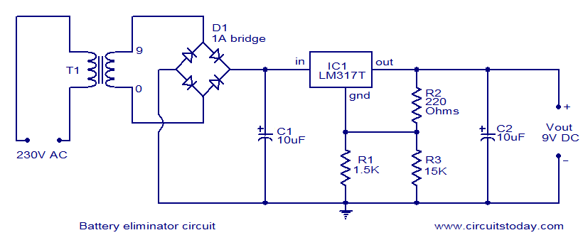
This document presents a circuit diagram of a battery eliminator circuit designed to replace 9V PP3 batteries. It can power any device that operates on a 9V battery. The transformer T1 reduces the mains voltage, while bridge rectifier D1...
Below is a comparator circuit that can measure the voltage of a car battery in 1-volt steps. The voltage indication is achieved through a comparison mechanism. The described comparator circuit is designed to accurately measure and indicate the voltage level...
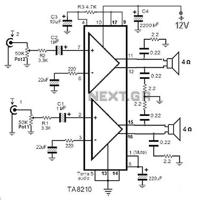
This circuit consists of a 2 x 22 watt BTL amplifier utilizing the IC TA8210AH. It functions not only as an automobile amplifier but is also suitable for low-frequency sound applications, particularly in high-fidelity audio systems, due to its...
The Up Alarm is designed to provide an audible alert when sunlight is detected or when a light source is activated in a dark environment. It can also be utilized to sense various light sources such as beams or...
The circuit is designed to fit into a small enclosure that can be placed in a backbox at a location of your choice. It requires only three wires: one for the battery positive voltage, one for the +5 volts...
This is a Courtesy Light Extender for vehicles. It extends the ON time of the interior lights when a door is closed, allowing passengers to see where they are seated. The Courtesy Light Extender circuit is designed to enhance the...
Warning: include(partials/cookie-banner.php): Failed to open stream: Permission denied in /var/www/html/nextgr/view-circuit.php on line 713
Warning: include(): Failed opening 'partials/cookie-banner.php' for inclusion (include_path='.:/usr/share/php') in /var/www/html/nextgr/view-circuit.php on line 713