
battery eliminator circuit

The battery eliminator circuit is structured to efficiently convert mains voltage into a usable 9V DC output for various electronic devices. The transformer (T1) is pivotal in this design, as it steps down the high voltage AC from the mains to a lower AC voltage suitable for rectification. Typically, a step-down transformer with a secondary output rating of around 9V to 12V is used, depending on the load requirements.
The bridge rectifier (D1), composed of four diodes arranged in a bridge configuration, performs the essential function of converting the stepped-down AC voltage into pulsating DC. This pulsating DC output is not suitable for most devices, hence the need for filtering to smooth the voltage.
Capacitor C1 acts as a smoothing filter, reducing the ripple in the DC output. The value of C1 is chosen based on the load current and the acceptable ripple voltage level; larger capacitance values will yield a smoother output, but will also increase the physical size and cost of the circuit.
The voltage regulation is handled by the LM317T integrated circuit, which is a versatile adjustable voltage regulator. It is capable of providing a stable output voltage, which is crucial for sensitive electronic devices. The output voltage can be set to 9V by selecting appropriate resistor values for R1 and R2, according to the formula provided in the LM317T datasheet. The resistor R3 can be used as a current limiting resistor or to set the minimum load current necessary for proper regulation.
In summary, this battery eliminator circuit is an effective solution for powering devices that require a 9V supply, offering a reliable and stable output while eliminating the need for disposable batteries. Proper component selection and configuration ensure that the circuit operates efficiently and meets the voltage and current requirements of the connected devices.Here is the circuit diagram of a battery eliminator circuit that can be used as a replacement for 9V PP3 batteries. The circuit given here can be used to power any device that operates from a 9V battery. The transformer T1 steps down the mains voltage and bridge D1 performs the job of rectification. Capacitor C1 is a filter. IC LM317T is the regul ator here. The value of R1, R2 and R3 are so selected that the output voltage of IC1 will be steady 9 volts. 🔗 External reference
Related Circuits
This circuit employs the widely used and easily accessible LM3914 integrated circuit (IC). The LM3914 is straightforward to operate, does not require external voltage regulators due to its built-in voltage regulation, and can be powered by a variety of...
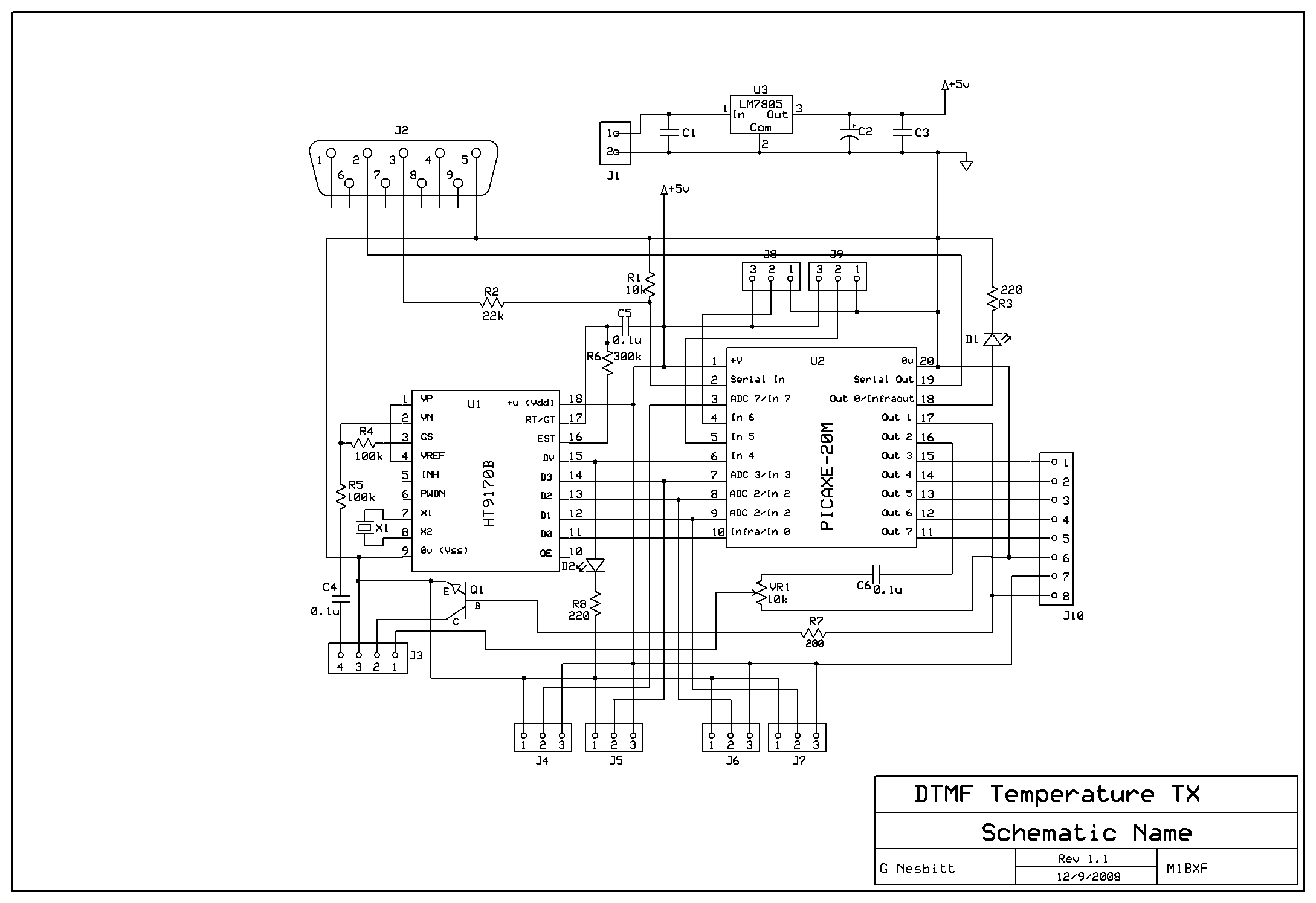
Remotely check the temperature of various items, specifically the repeater site at GB3PY. This system utilizes a radio to receive requests for the current temperature and sends the results back to the user. Requests are made using DTMF tones,...
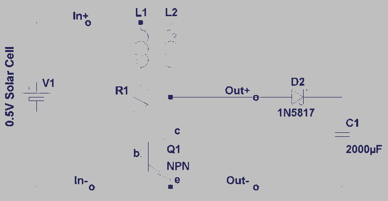
A steam engine-powered carousel project that utilizes the Joule Thief circuit. This project combines the classic charm of a steam engine with the innovative Joule Thief circuit, creating a unique carousel that operates efficiently. The steam engine serves as the...
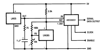
The circuit illustrates a Temperature to Digital Converter diagram utilizing the LM35 sensor, which includes a beneficial bypass capacitor connected from VIN to ground and a series RC damper. The described circuit employs the LM35 temperature sensor, a precision integrated...
This power supply was designed for use with the Simple hybrid amplifier published elsewhere in this issue. It is suitable for various applications as well. A cascade generator is utilized for the 170 V output, a switch-mode supply provides...
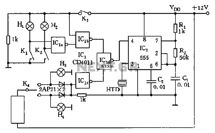
The circuit presented is a 555 timer-based alarm system for vehicles, which primarily consists of a 555 timer and a quad 2-input NAND gate configuration. It is designed to produce a long beep sound when oil pressure is low...