
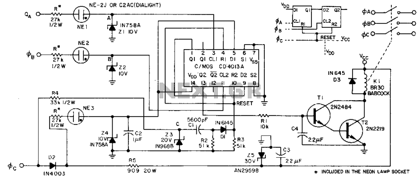
Phase-sequence detector II
No description available.
Related Circuits
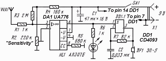
The circuit diagram of the non-contact voltage detector is illustrated in Figure 1. It consists of two main components: an AC amplifier and an audio oscillator, which is based on the Schmitt trigger DD1.1 of the IC CD4093, along...
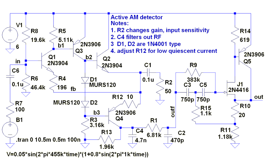
The following circuit illustrates an AM Broadcast Detector Circuit Diagram. Features include a 10 kHz notch filter, which is suitable for low voltage single supply applications. The AM Broadcast Detector Circuit is designed to demodulate amplitude modulated (AM) signals, allowing...
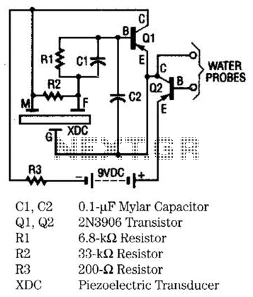
The moisture detector utilizes two transistors and a piezoelectric transducer to emit an alarm tone when water is detected. Transistor Q1 functions as a crystal-controlled oscillator, employing a portion of the piezoelectric transducer XDC, which consists of two piezoelectric...
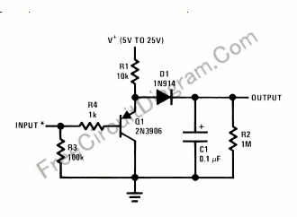
Using only a single transistor and a few passive components, a fairly sensitive peak detector circuit can be built. This peak detector circuit is suitable for various applications. The peak detector circuit utilizes a single transistor, typically configured in a...
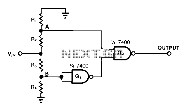
This simple window detector utilizes half of a 7400 quad NAND gate along with four resistors, selected to ensure that the voltage at point A exceeds the voltage at point B for any input voltage. When no input is...
This circuit is designed to detect electrical wires connected to the mains (live wire). It features an LED for visual indication and a buzzer for audio alerts. As the detector is brought closer to the electrical wire, the LED...