
Car battery monitor

The circuit comprises a battery voltage monitoring system utilizing a light-emitting diode (LED) as a visual indicator. The design incorporates a 10 K ohm potentiometer that allows for the adjustment of the voltage threshold at which the LED will activate. This threshold is crucial for determining the acceptable operating voltage range for the battery.
When the system is powered, the battery voltage is continuously monitored. If the voltage drops below the set threshold due to high current draw, such as during engine cranking, the voltage divider formed by the potentiometer and an additional resistor (if used) will trigger the LED. This LED serves as an alert to the user, indicating that the battery voltage has reached a critical level, which may suggest that the battery is either defective or in need of recharging.
The circuit can be implemented using a simple comparator configuration or an operational amplifier (op-amp) for more precise voltage detection. Additional components may include a resistor in series with the LED to limit current, ensuring the LED operates within its safe limits.
Overall, this circuit is an essential tool for monitoring battery health and ensuring that the vehicle's electrical system operates efficiently, preventing potential failures due to inadequate battery voltage.Warning light (LED) indicates when battery voltage falls below level set by 10 K pot Can indicate that battery is defective or needs charging if cranking drops battery voltage below preset "safe" limit. 🔗 External reference
Related Circuits
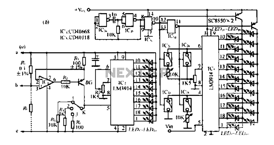
Figure A, B, and C illustrate the test rod end clip, with a positive power supply terminating test equipment. The B and C ends are connected in series with the load, where C represents the negative side of the...
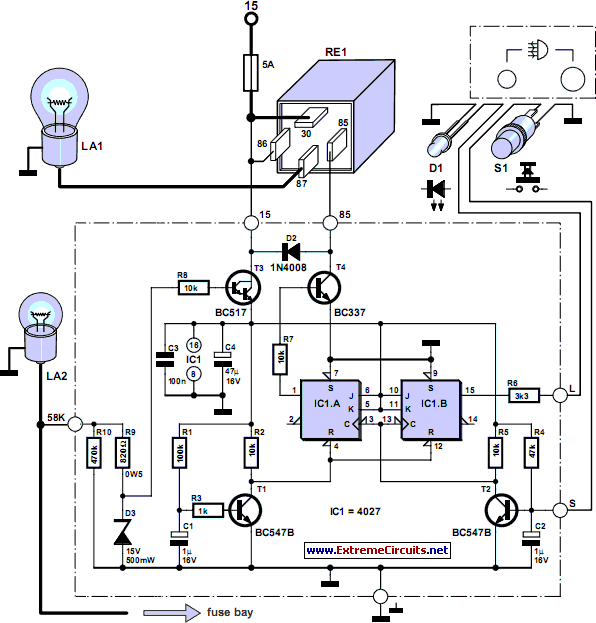
According to current legislation in many countries, vintage cars must also be fitted with a rear fog lamp. Modern vehicles incorporate circuitry associated with the fog lamp switch to prevent the fog lamp from activating when the lights are...
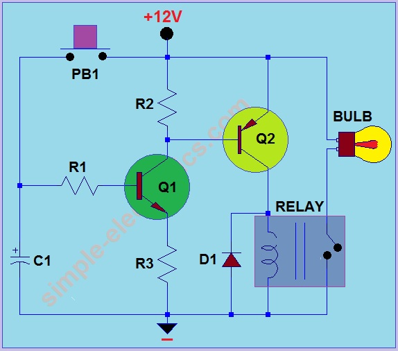
This circuit operates by activating a headlight when the push-button PB1 is pressed. The headlight remains illuminated for a predetermined duration, which can range from several seconds to minutes, before automatically turning off. When PB1 is engaged, capacitor C1...
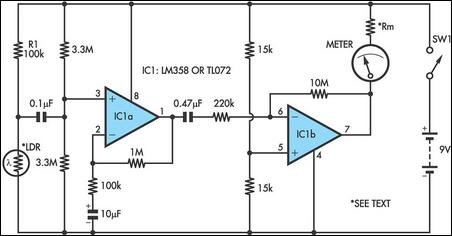
Strictly speaking, this simple circuit should not work. How could anyone expect an ordinary light-dependent resistor (LDR) photocell to detect the change in blood flow as the heart pulsates through a fingertip in natural daylight? The secret lies in...
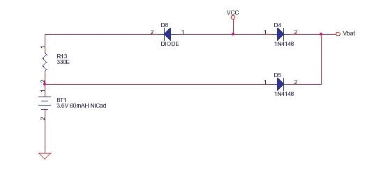
This circuit functions as a low-cost battery backup solution for SRAM and microcontroller/microprocessor applications. It utilizes 1N4148 diodes to prevent battery discharge back to the power source. Diode D8 provides a one-way path for charging the battery through resistor...
The battery life and operating cost of an electric vehicle are significantly impacted by the overdischarge of the battery. This circuit is designed to provide both a warning and a shutdown mechanism. An electronic switch is connected in series...