
rear fog lamp for vintage cars
The described circuit serves as an effective solution for integrating a rear fog lamp into vintage vehicles, ensuring compliance with current regulations while enhancing safety. The use of a dual JK flip-flop allows for the toggling functionality needed for the fog lamp operation, while the inclusion of a de-bouncing circuit ensures that the clock pulse generated by the push-button switch is stable and reliable.
The circuit design emphasizes safety by sourcing power from the number plate lamp, which serves as a failsafe against accidental activation when only parking lights are in use. The incorporation of a Zener diode voltage-limiter circuit is a critical design feature that protects sensitive components from voltage fluctuations, a common issue in older vehicles with mechanical regulators.
The relay activation mechanism is straightforward yet effective, allowing for the fog lamp to be energized only when required, thus preventing unnecessary use. The specification for low-current LED D1 aligns with modern requirements for vehicle lighting, providing visibility without drawing excessive power.
Overall, this circuit design is a practical approach to retrofitting older vehicles with modern safety features, ensuring compliance with legislation while enhancing the functionality of vintage cars. Proper installation and verification of connections will be essential for optimal performance and reliability.According to current legislation in many countries, vintage cars must also be fitted with a fog lamp at the rear. In modern cars, there is a bit of circuitry associated with the fog lamp switch to prevent the fog lamp from going on when the lights are switched on if the driver forgot to switch it off after the last patch of fog cleared up.
The cir cuit described here extends that technology back in time. The circuit is built around a dual JK flip-flop (type 4027). T3 acts as an emitter follower, and it only supplies power to the circuit when the lights are switched on. For safety reasons, the supply voltage is tapped off from the number plate lamp (L2), because it is on even if you accidentally drive with only the parking lights on.
The wire that leads to the number plate lamp usually originates at the fuse box. As the states of the outputs of IC1a and IC1b are arbitrary when power is switched on, the reset inputs are briefly set high by the combination of C1, R1 and T1 when the lights are switched on (ignition switch on). That causes both Q outputs (pins 1 and 15) to go low. IC1a and IC1b are wired in toggle mode (J and K high). The Set inputs are tied to ground (inactive). The driver uses push-button switch S1 to generate a clock pulse that causes the outputs of the flip-flops to toggle.
The de-bouncing circuit formed by C2, R4 and T2 is essential for obtaining a clean clock pulse, and thus for reliable operation of the circuit. C1 and C2 should preferably be tantalum capacitors. The Q output of IC1b directly drives LED D1 (a low-current type, and yellow according to the regulations).
The Q output of IC1a energizes relay Re1 via T4 and thus applies power to the rear fog lamp L1. Free-wheeling diode D2 protects T4 against inductive voltage spikes that occur when the relay is de-energised. In older-model cars, the charging voltage of the generator or alternator is governed by a mechanical voltage regulator.
These regulators are less reliable than the electronic versions used in modern cars. For that reason, a Zener diode voltage-limiter circuit (D3 and R9) is included to keep the voltage at the emitter of T3 below 15 V and thus prevent the 4027 from being destroyed by an excessively high voltage. The supply voltage for the circuit is tapped off from the fuse box. An accessory terminal is usually present there. Check to make sure it is fed from the ignition switch. The pushbutton switch must be a momentary-contact type (not a latching type). Ensure that the pushbutton and LED have a good ground connection. Fit the LED close to the button. 🔗 External reference
Related Circuits
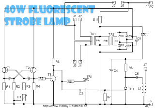
This circuit is designed for a 40 Watt fluorescent lamp. It operates similarly to a traditional strobe light, but utilizes a fluorescent tube instead. The fluorescent tube remains continuously energized, with both electrodes supplied with electricity. This current causes...
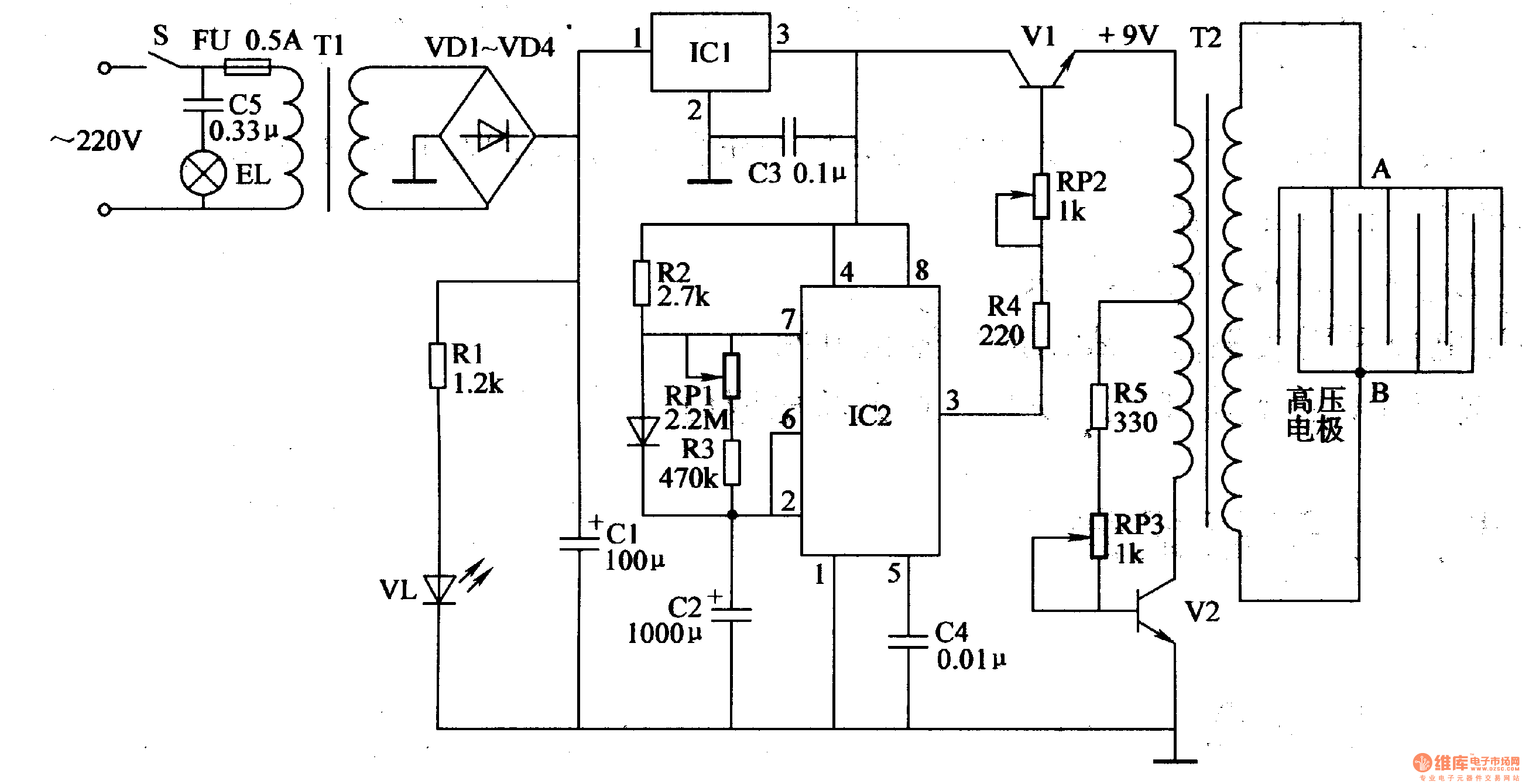
Working Principle: The circuit, as illustrated in figure 4-187, is composed of three main components: the power circuit, the pulse oscillator, and the high voltage generator. The power circuit includes components S, FU, TI, VD1-VD4, C1, C3, IC1, R1,...
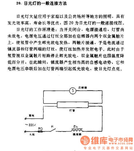
The general connection method for fluorescent lamps is utilized in residential and public lighting applications due to their luminous efficiency and long service life. The general wiring diagram for the lamp is illustrated in Figure 20. The working principle...
This design is intended as a dimmer for a 12V reading lamp, but it can also function as a motor speed controller for devices like drills. The circuit modulates the voltage supplied to the load, allowing for variable pulse...

The voice-activated lamp circuit consists of an operational amplifier FC52, a flip-flop made from two NAND gates TMY23A, a relay J, a piezoelectric crystal speaker Y, and additional components. The flip-flop processes the sound signal from the speaker, converting...
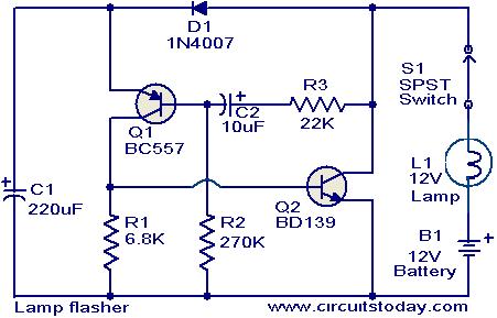
This simple circuit can be used to flash incandescent lamps with a power rating of up to 10W. It is ideal for creating flashing beacons on automobiles and similar applications. The circuit consists of an astable multivibrator utilizing transistors...