
Car Battery Saver Circuit
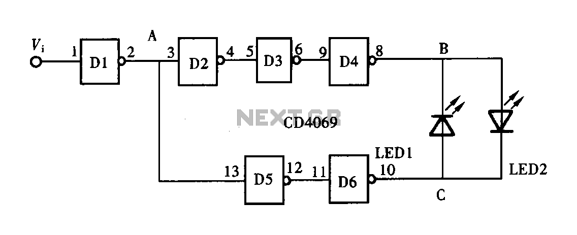
The described circuit functions as an automatic lamp control system activated by a door switch. The primary components include a switch (SW1), a capacitor (C1), a resistor (R1), and an integrated circuit (IC1) that contains a flip-flop and a comparator. Upon opening the door, SW1 closes, initiating the circuit and illuminating the lamp. The capacitor C1 charges gradually through the resistor R1, which controls the charging rate. The specific voltage threshold of 2/3 of the supply voltage at the comparator pins of IC1 is crucial for determining when the flip-flop state changes.
Once the voltage threshold is achieved, the internal comparator of IC1 triggers a change in the flip-flop state, resulting in a drop in voltage at pin #3 to zero. This action turns off the lamp, effectively creating a delay in illumination that is dependent on the charging time of C1. The lamp will remain off as long as the door is closed, ensuring energy efficiency and preventing unnecessary illumination.
The three-terminal configuration allows for easy integration with existing door switches and lamps. The two terminals connect the circuit in series with the lamp and the door switch, while the third terminal connects to a 12V power supply, providing necessary voltage for operation. Additionally, the circuit includes a bypass option through a standard switch, which permits the lamp to remain on continuously, regardless of the door's position. This feature can be useful in scenarios where constant light is desired, such as during cleaning or maintenance activities.
The use of dotted lines in the schematic indicates the optional bypass connection, clearly distinguishing it from the main circuit path. This design approach enhances the versatility of the lamp control system, catering to various user needs while maintaining straightforward operation and installation. Overall, this circuit exemplifies a practical application of electronic components to achieve an automated lighting solution that responds to user actions.When the door is opened, SW1 closes, the circuit is powered and the lamp is on. C1 starts charging slowly through R1 and when a voltage of 2/3 the supply is reached at pins #2 and #6 of IC1, the internal comparator changes the state of the flip-flop, the voltage at pin #3 falls to zero and the lamp will switch-off. The lamp will remain in the off state as the door is closed and will illuminate only when the door will be opened again. The final result is a three-terminal device in which two terminals are used to connect the circuit in series to the lamp and the existing door-switch. The third terminal is connected to the 12V positive supply. The circuit can be bypassed by the usually existing switch that allows the interior lamp to illuminate continuously, even when the door is closed: this connection is shown in dotted lines.
🔗 External reference
Related Circuits

This stereo amplifier utilizes the NE5517/A and features an excellent tracking accuracy of 0.3 dB, which is typical. The offset can be adjusted using the potentiometer, Rp. For AC-coupled amplifiers, the potentiometer can be substituted with two 5.1 k...
A logic pen, also known as a logic detection probe, is a commonly used tool for detecting the logic state at various points within digital circuits. The logic states in digital circuits are typically categorized into three types: a...
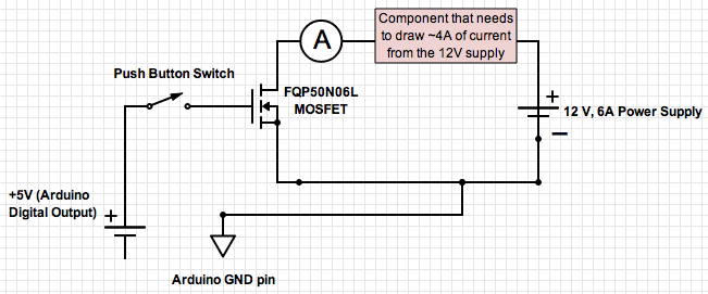
If the ground of the Arduino is disconnected from the negative terminal of the power supply, current flows through the MOSFET, even when the switch is not closed. In an electronic circuit involving an Arduino and a MOSFET, maintaining a...
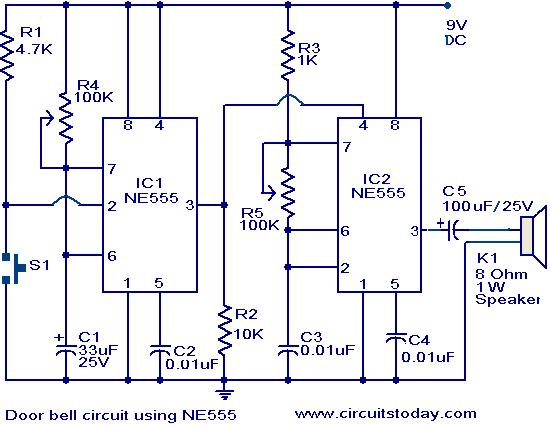
The primary components of this doorbell circuit are two NE555 timer integrated circuits (ICs). When switch S1 is pressed momentarily, the loudspeaker emits a bell tone for the duration determined by the monostable multivibrator configuration around IC1. Pressing switch...
This is a successful vacuum tube project featuring a small amplifier where a 6V6GT output pentode is connected in triode mode, producing an output of approximately 4.5 watts. The project includes a single-ended audio amplifier with a resistive input...
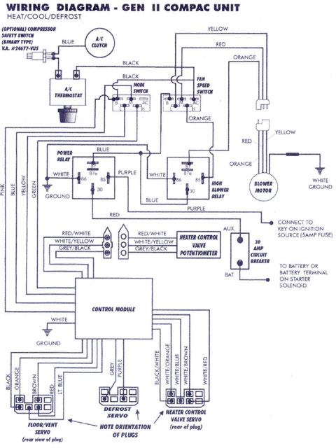
Mercury, Oldsmobile, Plymouth, Pontiac, muscle cars, and antique classic car wiring diagrams are continuously being added to this site. The wiring diagram for the Porsche 911L engine from the 1968 model has undergone changes since the original scheme. For...
Warning: include(partials/cookie-banner.php): Failed to open stream: Permission denied in /var/www/html/nextgr/view-circuit.php on line 713
Warning: include(): Failed opening 'partials/cookie-banner.php' for inclusion (include_path='.:/usr/share/php') in /var/www/html/nextgr/view-circuit.php on line 713