
Door bell circuit using NE555
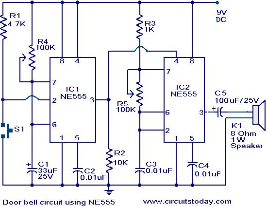
The circuit employs two NE555 timer ICs to create a functional doorbell system. The first timer, configured in monostable mode, is activated by pressing switch S1. This action triggers the timer, causing the output at pin 3 to go high, which energizes the loudspeaker for a duration determined by the resistor-capacitor (RC) time constant established by R4 and the timing capacitor. The output duration can be fine-tuned by adjusting the potentiometer R4.
Once IC1's output transitions high, it resets the second timer, configured in astable mode. This configuration allows IC2 to continuously oscillate, generating a square wave output that drives the speaker, producing a bell sound. The frequency of the oscillation, and thus the pitch of the bell tone, can be varied by adjusting potentiometer R5. This flexibility enables users to customize the audible alert according to their preferences.
The circuit's design showcases the versatility of the NE555 timer ICs, which are widely used in various applications due to their reliability and ease of use. For individuals seeking to deepen their understanding of the 555 timer and its applications, several educational resources are available, including reviews of notable books that cover 555 timer circuits and projects in detail. These resources can serve as valuable tools for enhancing knowledge and practical skills in electronics.The main part of this doorbell circuit are two NE555 timer ICs. When some one presses switch S1 momentarily, the loud speaker sounds a bell tone as long as the time period of the monostable multivibrator built around IC1. When the switch S1 pressed, IC1 is triggered at its pin 2 and output pin 3 goes high for a time period previously set by the val
ues of POT R4 and POT R5. When the output ofIC1 goes high it resets IC2 and it starts to oscillate to make a bell sound through the speaker. The IC2 is configured as an astable multivibrator whose oscillation frequency can be varied with the help of POT R5.
By adjusting the values of R4 & R5, modifications on the tone are possible. If you are not familiar with the basics of 555 timer IC, and its applications, you can buy books that will help you get a better understanding from our online store. Totally 3 books have been reviewd in detail along with their authors. You can get their reviews and buy them here:- 3 Great Books to Learn 555 Timer Circuits and Projects 🔗 External reference
Related Circuits
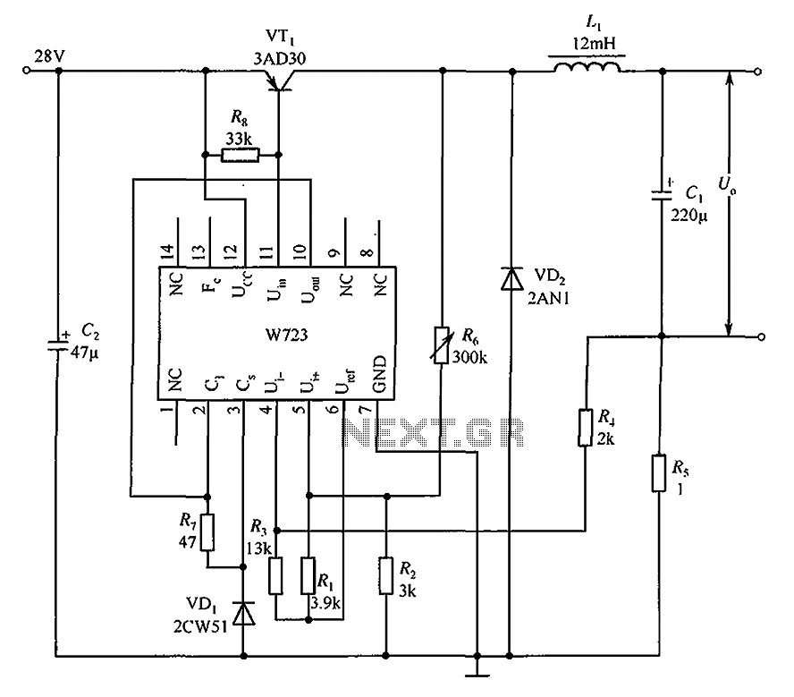
The Multiport W723 is an adjustable constant current regulator designed for use in switching regulator circuits, capable of delivering an output current of 1A. In the illustrated circuit, the W723 reference base voltage is approximately 7.2V. This voltage is...
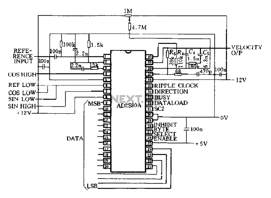
The AD2S80A represents a typical application circuit, detailing specific peripheral connectivity and device parameters. It is configured for a 12-bit resolution (SCl-0, Sc2 1) to select a reference frequency of 5 kHz. The bandwidth is 520 Hz, with a...
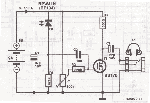
This wireless headphones transmitter ensures quality reception over a distance of 2 meters. The oscillator frequency ranges from 1750 kHz to 3500 kHz, and for the antenna, it... The wireless headphones transmitter operates within a frequency range of 1750 kHz...
Here is an interesting circuit for a magnetic proximity switch which can be used in various applications. The magnetic proximity switch circuit, in principle, consists of a reed switch at its heart. When a magnet is brought in the...

This design circuit for audio amplifiers with DC coupling to the load is not commonly used today, despite its clear advantages. One advantage is the elimination of the need for a second (symmetric) power supply, and another is the...
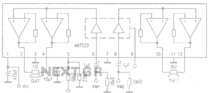
AN7522 is a Panasonic stereo audio amplifier IC that delivers an output power of 3W at 8 ohms. It features a standby function, low static power consumption, and reduced noise levels, requiring fewer external components for stable operation. This...
Warning: include(partials/cookie-banner.php): Failed to open stream: Permission denied in /var/www/html/nextgr/view-circuit.php on line 713
Warning: include(): Failed opening 'partials/cookie-banner.php' for inclusion (include_path='.:/usr/share/php') in /var/www/html/nextgr/view-circuit.php on line 713