
Car Door Keypad Electronic
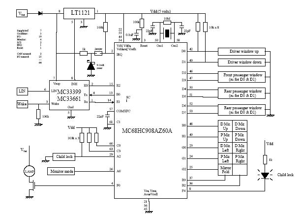
The Car Door Keypad Electronic Circuit is designed to enhance vehicle security by providing a user-friendly interface for locking and unlocking car doors. This circuit employs the MC68HC908AZ60A microcontroller, which is known for its efficiency and compact design, making it ideal for automotive applications.
The circuit typically consists of a keypad, which allows the user to input a security code. The microcontroller processes the input signals from the keypad and compares them to a pre-stored code in its memory. If the entered code matches the stored code, the microcontroller activates a relay or an electronic lock mechanism to unlock the car doors.
The schematic may include additional components such as resistors for pull-up or pull-down configurations, capacitors for noise filtering, and diodes for protection against reverse polarity. Power supply considerations are also crucial; the circuit should be designed to operate within the vehicle's standard voltage range, typically 12V.
In terms of layout, the circuit should minimize the length of connections to reduce electromagnetic interference, and components should be arranged to facilitate easy troubleshooting and maintenance. The use of a lower pin-count design not only reduces the overall cost of the circuit but also simplifies the PCB layout, allowing for a more compact design that can be easily integrated into the vehicle's existing systems.
Overall, this Car Door Keypad Electronic Circuit offers a reliable and efficient solution for vehicle access control, combining functionality with cost-effectiveness.The following circuit shows about Car Door Keypad Electronic Circuit Diagram. Features: lower pin-count lower cost device, uses an MC68HC908AZ60A, .. 🔗 External reference
Related Circuits
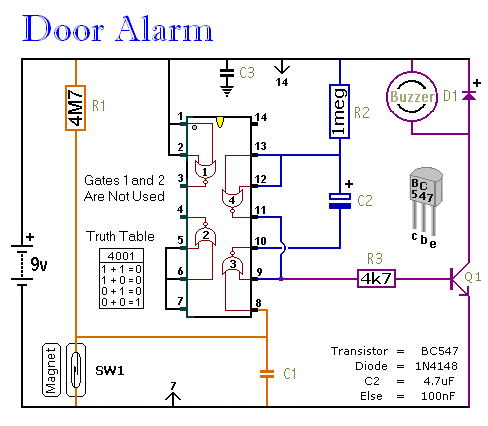
This is a straightforward and easy-to-assemble multi-purpose alarm system. It can be constructed using stripboard or veroboard along with a few inexpensive, readily available components. The alarm is designed to be installed on doors, windows, sheds, garages, cupboards, and...
The heart of the lock is the 40022 octal counter. When first powered C2 is charged via R5 so the reset input of the counter is kept high. That causes output Q to go high while all the other...
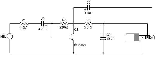
Most sound card microphone inputs require a minimum signal level of at least 10 millivolts, but some older 8-bit cards need as much as 100 millivolts. The typical impedance of the PC sound card microphone input is in the...
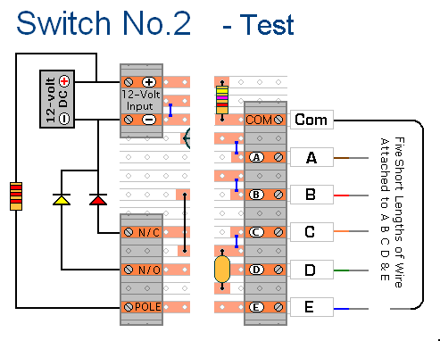
The prototype of Keypad Switch No. 2 was constructed using only the stripboard layout as a reference. If the layout has been accurately reproduced, a functional circuit will result. Once the layout is confirmed to be correct and a...
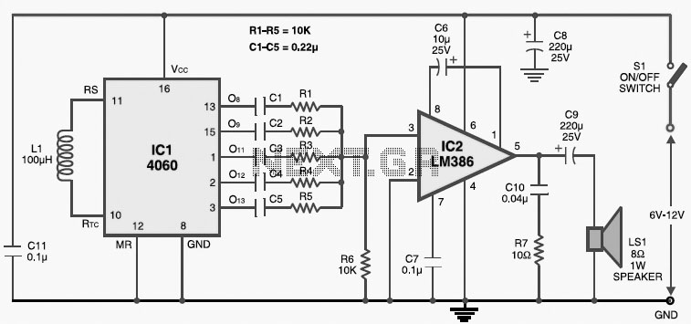
This multitone electronic siren is useful for burglar alarms, reverse horns, etc. It produces five different audio tones and is much more attention-grabbing than a single-tone siren. The circuit is built around the popular CMOS oscillator-divider IC 4060 and...
This circuit provides a delayed visual indication when a doorbell switch is pressed. Additionally, a double pole double throw (DPDT) switch can be activated from within the house to light a lamp at the doorbell switch. The lamp can...