
Keypad Operated Switch No.2 - testing your circuit
Once powered on, the relay should activate, illuminating the yellow LED while the red LED remains off. The "Common" wire should be touched sequentially to "A," "B," "C," and "D," causing the relay to deactivate, the yellow LED to turn off, and the red LED to light up. The "Common" wire should then be momentarily touched to "E," which should reactivate the relay, turning off the red LED and lighting the yellow LED. This process can be repeated until the circuit operates correctly. Entering the four-digit code should deactivate the relay, while touching the "Common" wire to "E" should reactivate it. The final test involves verifying that entering an incorrect number prevents the code from functioning. This can be done by touching "E" to activate the relay, followed by "A," "B," "E," "C," and "D." The relay should not deactivate, and touching "E" after "A," "B," or "C" should also cause the code entry to fail.
If any issues arise during testing, a detailed inspection of the circuit board is recommended to identify the source of the problem. Areas where the board has been cut should be checked for loose strands of copper left by the saw. Additionally, the board should be examined for short circuits caused by component leads touching each other. If an LED does not light up, its orientation should be verified. It is also possible for the stripboard itself to be defective, as there have been instances where copper tracks were not completely severed during manufacturing. If the circuit has been built using the specified components and the step-by-step construction guide has been followed, any faults are likely to be minor, such as a component connected incorrectly, a missing or unwanted solder bridge, or an incomplete track cut. If no obvious issues are found, a systematic approach to troubleshooting should be adopted. This includes double-checking that all track cuts have been made accurately and completely, utilizing a magnifying glass and backlighting the board to identify any small strands of copper that may be causing issues.The prototype of Keypad Switch No. 2 was built using only the Stripboard Layout as a guide. So - if you have faithfully reproduced that layout - you will have a working circuit. Once you`re satisfied that your layout is correct - and you have made a careful and thorough check of the underside of the board - it`s time to power-up the circuit and tes t its operation. This is always an anxious moment. If you construct a lot of circuits - you might consider building the Current Limiting Power Supply - or alternatively - you could add the Simple Current Limiter to your existing PSU. Both will let you set an upper limit on the amount of current supplied to your circuit - and so protect it from any serious damage.
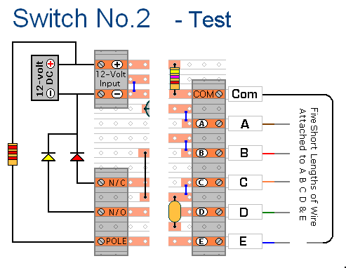
A resistor and a couple of LEDs are all that`s needed to demonstrate that the relay contacts are switching properly - and you can simulate the keypad-switches using short lengths of wire. Connect five short lengths of wire to the "A B C D & E " terminals. Connect a longer piece of wire to the "Com" terminal. You`re going to touch the short wires with it - so it needs to be long enough to reach as far as "E".
Strip a little of the insulation from the ends of all six wires. = Connect a 2k2 resistor between the "+" terminal and the "Pole" Terminal. Connect an LED from the "N/C" terminal to the negative line. Connect another LED from the "N/O" terminal to the negative line. I used two different colour LEDs in the diagram because - in what follows - I wanted to be able to distinguish between them. You can use whatever colours you have available. = Finally, connect the 12-volts DC to the input terminals. Pay particular attention to the polarity of the supply. Note that the positive connection goes to the top terminal. = Turn On The Power The relay should energize - the yellow LED should light - and the red LED should be off.
Touch the "Common" wire in turn to "A" then "B" then "C" then "D". The relay should de-energize - the yellow LED should turn off - and the red LED should light. = Next, touch the "Common" wire momentarily to "E". The relay should energize - the red LED should turn off - and the yellow LED should light. Repeat the test as often as you like - until you`re satisfied that your circuit is operating correctly. Entering the four digit code should de-energize the relay - and touching the "Common" wire to "E" should energize it.
= The final test is to check that entering a "wrong number" prevents the code from working. Start by touching "E" to energize the relay. Then touch "A B E C D". The relay should not de-energize. Touching "E" after "A, B or C" should cause the code entry to fail. = If - in the course of the test - you find that something is not working properly, then a careful inspection of the relevant area of the circuit board should turn up the cause of the problem. Where you`ve cut the board to size - look for small loose strands of copper left behind by the saw. Check the board for short-circuits caused by component leads touching each other. If an LED is not lighting - check that it`s connected the right way round. It can also happen that the stripboard itself is faulty. I have seen cases where the copper tracks have not been completely severed from one another during manufacture.
If you`ve built your circuit using the specified components - and you`ve followed the step-by-step construction guide described on the Support Page - then the chances are that any bug will be caused by something minor - a component connected the wrong way round - a missing or unwanted solder bridge - an incomplete cut in the track etc. If you can`t see anything obvious then adopt a systematic approach to faultfinding. Begin by double-checking that all of the cuts in the tracks have been made - that they are all In The Right Place - and that they sever the track completely.
Use a magnifying glass - and backlight the board. It only takes the smallest strand of copper t 🔗 External reference
Related Circuits

The video amplifier circuit utilizes the LM359 integrated circuit, which is a dual, high-speed, programmable current mode (Norton) amplifier. This circuit is suitable for general-purpose video amplification applications. The LM359 is designed to operate as a high-speed amplifier, making it...
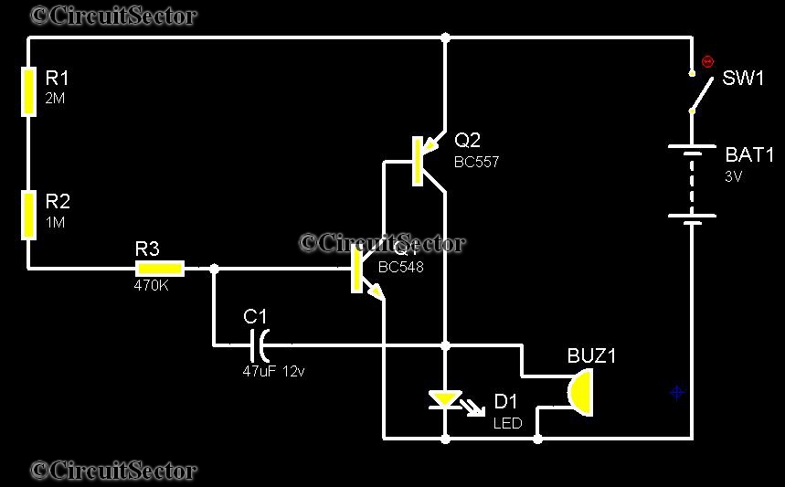
Telephones are declining globally; however, India has over 350 million mobile phone users, alongside a significant number of traditional telephone users. This telephone timer is designed to save costs by controlling unnecessary time spent during phone calls. This simple...

The TDA2050 integrated circuit can be used to design a simple high-fidelity audio power amplifier, intended for use as a Class AB audio amplifier. Due to its high power capabilities, the TDA2050 audio power amplifier can deliver up to...
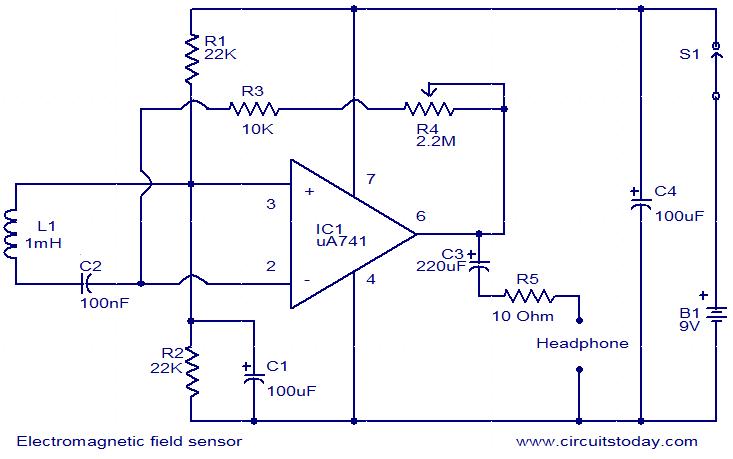
This is a very simple circuit that can be used to sense electromagnetic radiations. The circuit can even detect hidden wires. A 1mH inductor is used for sensing the electric field. The electric field will induce a small voltage...
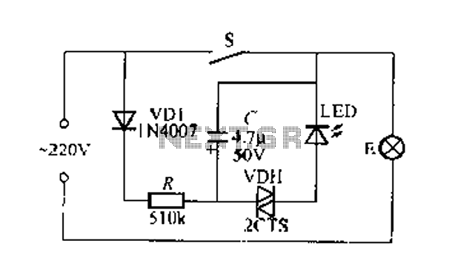
Figure 2 illustrates a circuit for a flashing light switch indicator. When switch S is closed, the normal light E illuminates, while the flashing light indicates a power loss when the system is not operational. When switch S is...
The image below displays the schematic diagram of the SPI Flash programmer hardware interface. Power for the interface can be supplied using either a 9V DC adapter or a 9V battery. The 74HCT367 integrated circuit (IC) buffers the adjacent...
Warning: include(partials/cookie-banner.php): Failed to open stream: Permission denied in /var/www/html/nextgr/view-circuit.php on line 713
Warning: include(): Failed opening 'partials/cookie-banner.php' for inclusion (include_path='.:/usr/share/php') in /var/www/html/nextgr/view-circuit.php on line 713