
Sound card microphone

The microphone input circuitry of PC sound cards, especially those from Creative Labs such as the Sound Blaster series, is designed to accommodate a variety of microphone types, primarily focusing on electret microphones due to their favorable characteristics. The input stage typically requires a minimum signal level of 10 millivolts, with older models demanding up to 100 millivolts, highlighting the importance of selecting the appropriate microphone for compatibility.
The microphone jack, commonly a 3.5mm (1/8 inch) pink stereo connector, features a specific pinout where the positive DC bias voltage is usually routed to the ring. However, variations exist, with some non-standard cards wiring the bias to the tip. This voltage is essential for powering the internal FET buffer within the electret microphone, which converts the high impedance of the microphone element to a more manageable level for the sound card input.
For optimal performance, especially in applications requiring stereo input, the circuit design allows for bias voltage to be supplied to both the tip and the ring. This configuration is particularly beneficial in advanced applications such as speech recognition and noise cancellation, where accurate signal capture is critical. The use of unidirectional electret microphones is recommended to enhance performance in noisy environments by minimizing background noise.
In cases where traditional connection methods do not yield satisfactory results, alternative circuit designs can be employed to interface electret microphones with older sound card models. These modifications typically involve the use of resistors and capacitors to ensure proper biasing and signal integrity.
Overall, the integration of electret microphones into PC sound card systems provides a versatile solution for various audio applications, leveraging their compact size, durability, and cost-effectiveness while ensuring compatibility across different sound card models and configurations.Most sound card microphone inputs require a minimum signal level of at least 10 millivolts, but some older 8-bit cards need as much as 100 millivolts. The typical impedance of the PC soundcard microphone input is in order of 1 to 20 kohms (can vary from card to card).
The microphone type which works best with computer sound cards is the electret microphone. Sound Blaster soundcards (SB16, SB32, AWE32, AWE64 or Live) from Creative Labs have a 3. 5mm (1/8 inch) pink stereo jack for the microphone input, with the following pinout: Note: Most soundcards will wire the positive DC bias voltage to the ring, but a small number of non-standard soundcards can have the bias voltage wired to the tip. A few cards have a jumper which enables or disables the power to the microphone jack. If the jumper is put on, the bias voltage ( +5V through a few kiloohm resistor) is wired to the tip. Newer mainboards with stereo microphone support will provide the bias voltage for both the tip and ring.
The approximate schematic of a Sound Blaster microphone input circuitry shows that the +5V voltage on the connector is heavily current limited. The card`s voltage might not be exactly 5V, but it is usually something between 3 and 5 volts when no microphone is connected.
The electret microphone is the cheapest omnidirectional microphone you can buy. Very sensitive, durable, extremely compact in size, electret mics are used in many applications where a small and inexpensive microphone with reasonably good performance is needed. You can find them in almost every stereo equipment, in consumer video cameras, mobile phones and so on.
The electret is a modified version of the classic capacitor microphone, which exploits changes in capacitance due to mechanical vibrations to produce a small voltage proportional to sound waves. The electret does not need an applied (or phantom) voltage like the condenser microphone - as it has a built-in charge - but a few volts are still required to power the internal Field Effect Transistor (FET) buffer.
The bias is needed for the small built-in FET follower which converts the very high impedance of the electret element (tens of megohms) to an acceptable level (several kohms). The circuit on the left shows a safe way to connect electret microphone capsules to old, non-standard soundcards.
Build this circuit only if the simple schematic below does not work. A simple modification which works with most soundcards is presented on the right. The circuit works because usually the power is fed to the microphone connector through a few kohm resistor and the DC bias on the tip is removed by the input capacitor inside the card. Note: A few, recently manufactured PCs have implemented true stereo microphone inputs. High performance speech recognition and advanced noise canceling applications - see the Andrea Superbeam Array stereo microphone - make good use of this new feature, providing more accurate and reliable signals in noisy environments.
When the stereo mic input mode is selected, the bias voltage will be provided for both the tip and the ring. The wiring for a stereo microphone is simple - see the schematic diagram on the left - connect the shield of both microphones to the sleeve of the plug, the left mic to the tip and the right mic to the ring.
For best performance, use unidirectional electret microphones. Quality dynamic microphones usually do provide sufficient signal to drive a reasonably good computer sound card. All you must do is to wire the mic properly, and in some cases, turn on the mic preamplifier built into the sound card (called `mic boost` on most PCs).
The connection is as simple as it gets: wire the microphone to the tip and sleeve of the sound card`s microphone input. Leave the ring (bias) pin open, do not connect it to anything. Most professional mics will be fitted with the standard XLR connector. To make a simple adaptor, wire the mic audio (XLR pi 🔗 External reference
Related Circuits
This is a microphone preamplifier designed for compatibility with a SoundBlaster AWE 64 sound card. It is also suitable for any compatible tag or PC audio input that provides a 5 Volt supply through a 2.2kΩ current-limiting resistor located...
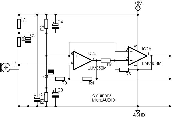
After conducting new experiments on sound analysis, a different design for the microphone amplifying section has been developed. The entire circuit is powered by a clean voltage supply ranging from +5V to +12V, which is filtered by capacitor C5....
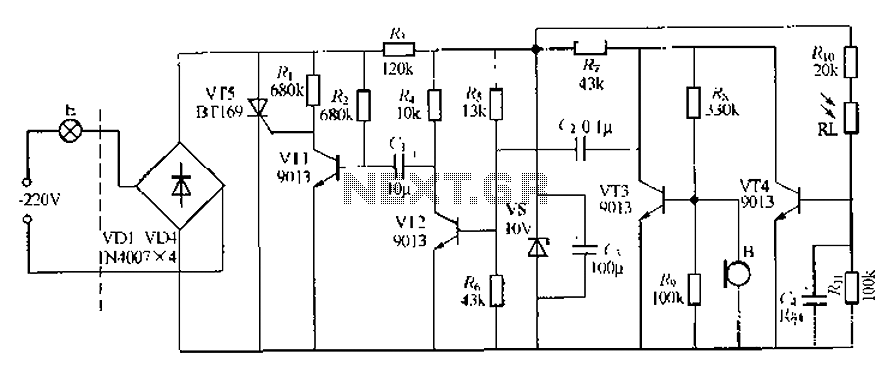
This circuit describes a sound and light control delay system for a walkway stairs light switch. It involves various components including 220V AC electric bulbs, diodes (VD1-VD4), and resistors. The circuit utilizes a rectifier regulator to stabilize the voltage...
The Bachmann Big Hauler locomotive has significantly improved in appearance, reliability, and noise level over the past few years. However, the sound system remains basic, providing a poor imitation of exhaust sounds in the form of a chuff synchronized...
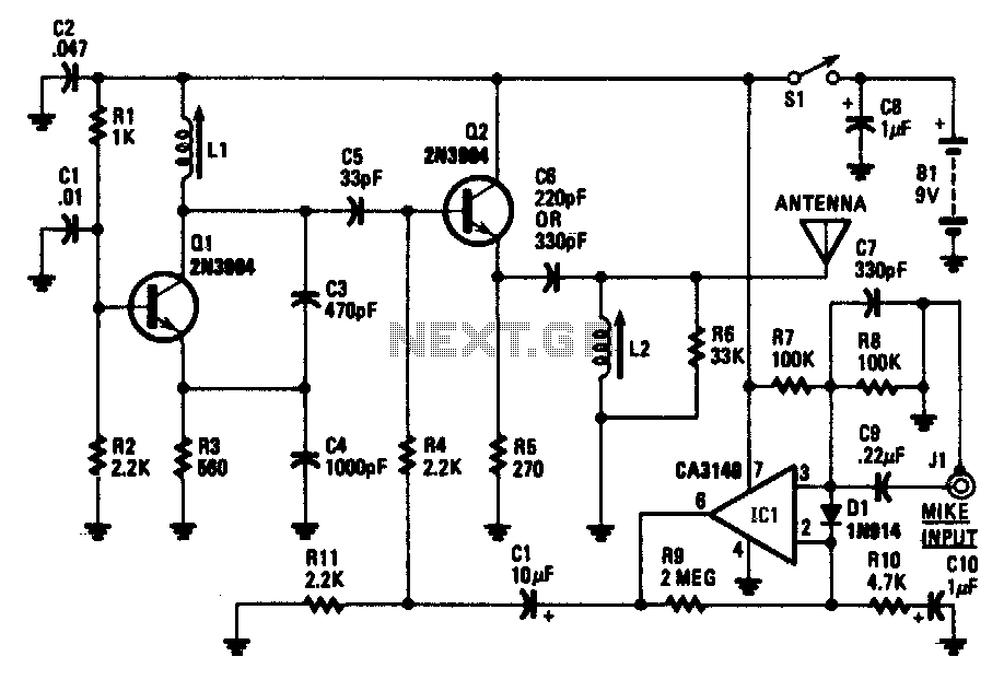
The transistor Q1 and its associated components form a tunable RF oscillator. The RF signal is directed to transistor Q2, which functions as the modulator. Operational amplifier IC1 amplifies the audio signal and transmits it through resistor R4 to...
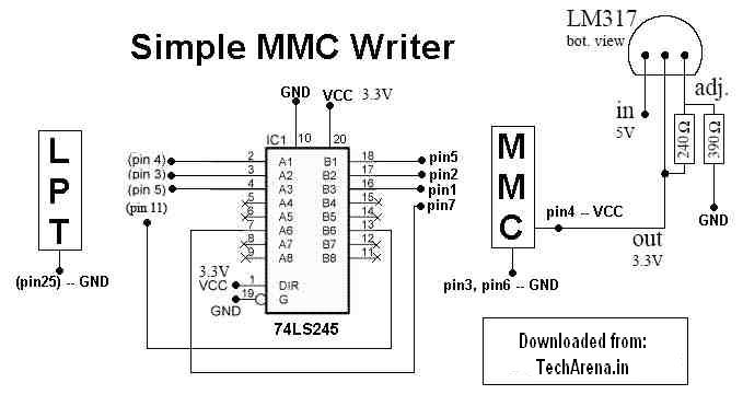
MMC Programmer - Memory Card Unlocker, Portable Devices, Handhelds, palmtops, cellphones, PDAs, pocket organizers, and all those other devices that make computing part of your lifestyle. The MMC Programmer is a specialized device designed for unlocking memory cards, specifically MultiMediaCards...