
car exterior lights electronic circuit

The exterior lighting system of a vehicle is a complex network of electrical components that work together to ensure visibility and safety during operation. The system begins with the power source, typically the vehicle battery, which feeds through a fusible link that acts as a protective measure against overcurrent conditions. The junction block serves as a central hub for distributing power to various circuits, including those dedicated to the tail light relay and the combination lights.
The tail light relay is crucial for controlling the operation of the rear lights, while the cruise control system may integrate with the lighting system to ensure that the vehicle's indicators function correctly when cruise control is engaged. The stop light switch is activated when the brake pedal is pressed, signaling the stop lights to illuminate, thus alerting drivers behind the vehicle.
The relay box houses various relays that manage the operation of different lights, including the front and rear combination lights and the license light. The column switch allows the driver to control the turn signals and hazard lights, which are essential for indicating lane changes and emergencies. The turn-signal and hazard flasher unit regulates the blinking of these lights, providing clear visual signals to other road users.
Additional components such as the park/neutral position switch and the back-up light switch play vital roles in ensuring that the vehicle's lights operate effectively in response to the vehicle's operational state. The combination meter may provide the driver with visual indicators of the system's status, including warnings for any malfunctions.
Overall, the intricate wiring and connections between these components must be carefully designed and implemented to ensure reliability and compliance with automotive standards. Proper insulation, secure connections, and appropriate gauge wiring are essential to prevent electrical failures and ensure the safe operation of the vehicle's exterior lighting system.Connection and wiring between each parts and component of exterior lights system of the vehicle such as the fusible link, junction block, tail light relay, cruise control, stop light switch, relay box, column switch, rear combination light, front combination light, license light, hazard light switch, turn-signal and hazard flasher unit, park/neutral position switch, back-up light switch, combination meter, and many more. 🔗 External reference
Related Circuits
This circuit utilizes a single 555 Timer IC and a small transformer to generate high voltage for testing zener diodes with voltage ratings up to 50VDC. The 555 timer operates in astable mode, with the output at pin 3...
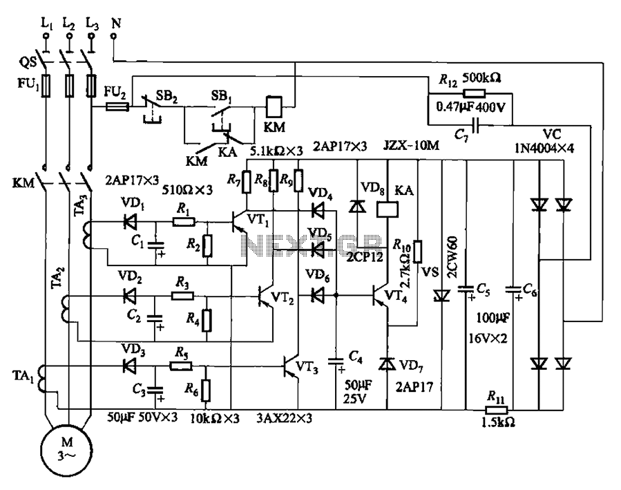
The current detection signal is obtained from three current transformers after rectification and filtering, resulting in three DC voltage outputs. These voltages are applied to transistors VT1, VT2, and VTa between the base and emitter. The signal is amplified...
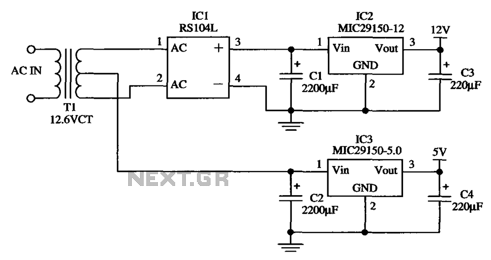
The low-cost dual output voltage regulator circuit is composed of two Micrel company regulators, the MIC29150-12 and the MIC29150-5.0. The dual output voltage regulator circuit utilizes the MIC29150 series from Micrel, which are low-dropout (LDO) voltage regulators designed for various...

This is a USB sound card featuring the PCM2902 chip. It was designed to test the D/A converters and includes a simple circuit based on the PCM2902. The sound card is equipped with analog input and output, an electrical...
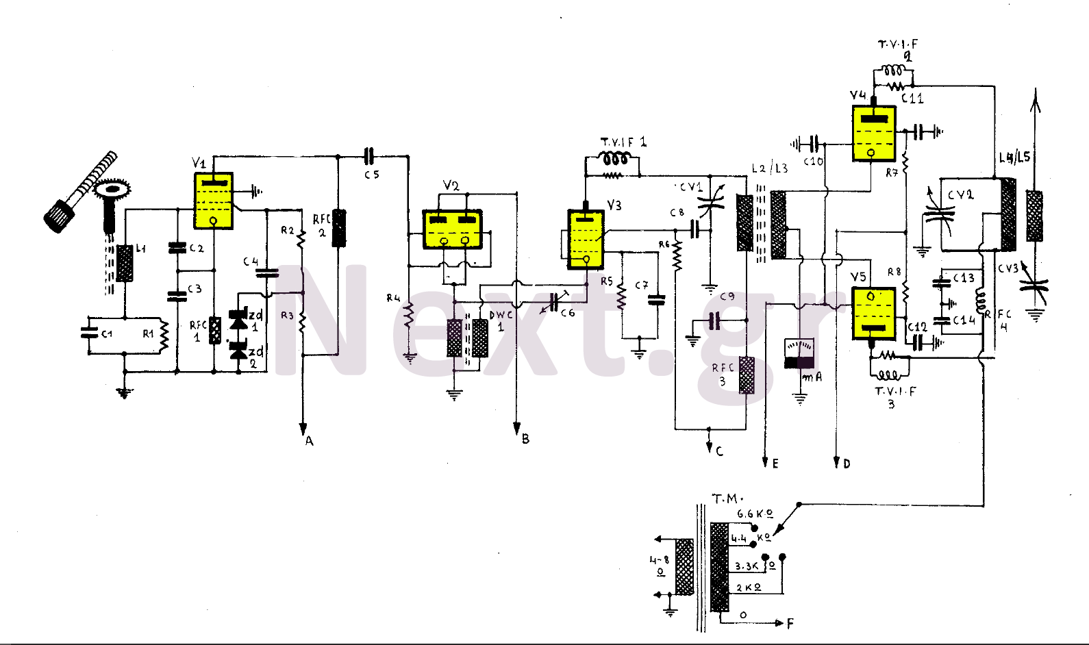
This 255W transmitter operates using coils designed for both medium and short waves. The antenna power is set at 255W and includes four operational states. The first state utilizes an EF80 tube functioning as a Colpitts Clapp oscillator. Frequency...
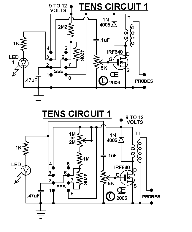
The circuits were originally designed for an individual with muscle issues. Although they were reported to function effectively, the use of these devices is not recommended for anyone, and no responsibility or liability is accepted for their assembly or...