
Detected line current Phase protective circuit 2
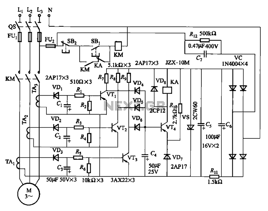
The described circuit utilizes three current transformers (CTs) to monitor current levels in an electrical system. Each CT outputs a proportional AC current that is subsequently rectified and filtered to provide stable DC voltages. These DC outputs are fed into three separate transistors (VT1, VT2, and VTa), which serve as amplifiers and switches for the signals derived from the CTs.
The amplified signals are then processed by a series of diodes, including VD4, VDs, and VD6, which ensure that only positive voltage signals are passed through for further processing. The OR gate circuit plays a crucial role in the logic of the system, allowing for multiple input signals to control the state of transistor VT4. When the conditions are met (i.e., one or more of the input signals are high), VT4 is activated, which in turn controls the relay KA.
Relay KA is responsible for managing the operation of contactor KM, which is used to control the motor's power supply. When a power shortage is detected, relay KA engages, signaling contactor KM to open and subsequently stopping the motor. This protective feature is critical for preventing damage to the motor during low power conditions.
However, a limitation of this protection circuit arises when the motor's stator windings are configured in a star connection. In this scenario, even during a power shortage, the phase current may not drop to zero due to the characteristics of the star configuration. As a result, the relay may not actuate as intended, potentially leaving the motor unprotected during critical conditions. This issue highlights the need for careful consideration of the motor's winding configuration when designing protective circuits to ensure reliable operation. By the three current transformers Current detection signal obtained after rectification, filtering the output of the three DC voltage, are applied to the transistor VTi, VT2 an d VTa between the base and emitter. Signal by three three- diode after amplification, received by the diode VD4, VDs, or gates VD6 thereof. By the OR gate circuit controls the transistor VT4 turned on or off to control the inter-pull or release of relay KA.
When the power shortage phase, KA pull, the contactor KM release, the motor stops. The disadvantage of the protection circuit, when the stator windings when -shaped connection inside the motor winding down phase current does not drop to zero, and the relay will not action.
Related Circuits
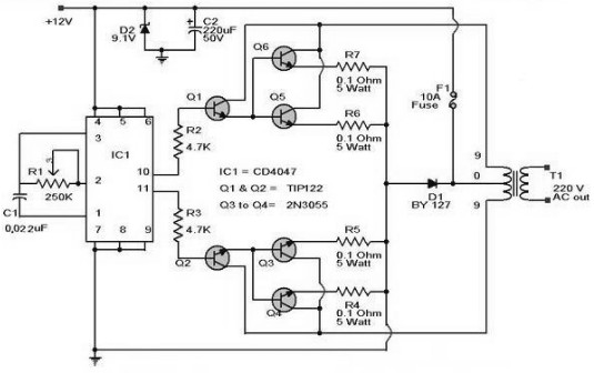
A 12 V car battery can be utilized as the 12 V input power source. The potentiometer R1 can be adjusted to achieve a 50 Hz output frequency. It is recommended to use a 10 A fuse in series...
Examples of an OFDM modulation system. The graph illustrates the input data signal (.... --- Ol01100) and the data signal by the string. The input signal is separated into components such as "00", "ll", "10", "00", "01", and other...
This circuit features a white LED-based emergency light that provides several benefits. It is exceptionally bright due to the incorporation of white LEDs. The light activates automatically when the mains supply is interrupted and deactivates when mains power is...
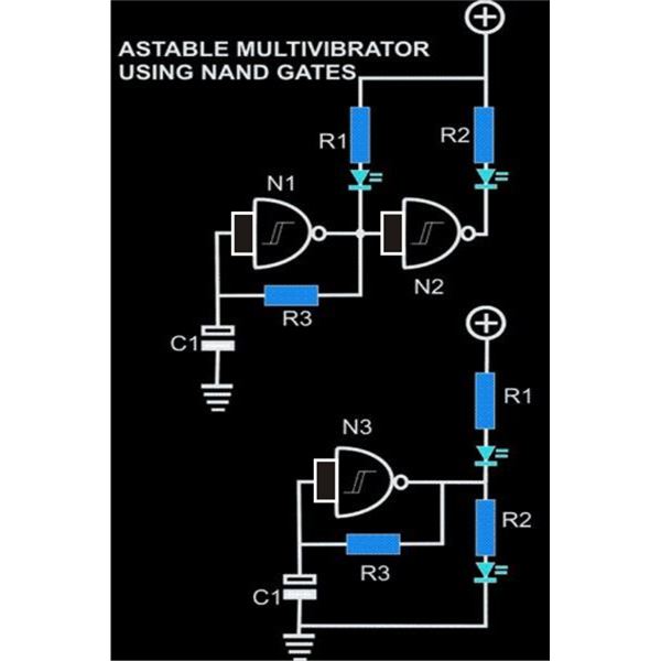
An astable multivibrator is an electronic configuration that generates continuous alternating high and low pulses from two outputs operating in tandem. The IC 4093 consists of four individual NAND gates in one package, specifically Schmitt trigger types, which provide...
This circuit utilizes the power MOSFET IRF840 for a 60-watt linear amplifier. The IRF series of power transistors are available in various voltage and current ratings. The described circuit employs the IRF840, which is a high-voltage N-channel MOSFET, suitable for...
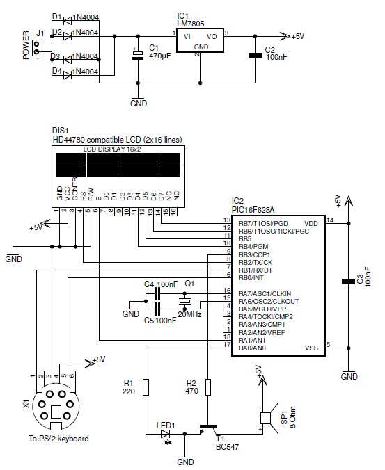
This PIC-based hardware circuit accepts texts from a PS/2 keyboard and converts it into a Morse code audio signal. The described circuit utilizes a PIC microcontroller to interface with a PS/2 keyboard, allowing for the input of alphanumeric characters. The...
Warning: include(partials/cookie-banner.php): Failed to open stream: Permission denied in /var/www/html/nextgr/view-circuit.php on line 713
Warning: include(): Failed opening 'partials/cookie-banner.php' for inclusion (include_path='.:/usr/share/php') in /var/www/html/nextgr/view-circuit.php on line 713